11
RROOOOFF IINNSSTTAALLLLAATTIIOONN
EEXXTTEERRIIOORR--PPOOWWEERR VVEENNTTIILLAATTOORR
VVEEVV11220000--EExxtteerriioorr PPoowweerr VVeennttiillaattoorr ((11220000 CCFFMM))
(also see instructions supplied with ventilator kit)
1. Locate the blower on the rear slope of the roof.
Place it in a location to minimize duct run. The
location should be free of obstacles (T.V. leads,
electrical lines, etc.). Bear in mind, if the blower top
is level with the roof peak, it will not be seen from
the street. Keep this approximate location in mind
as you work from within the attic.
2. Mark a point halfway between rafters.
3. Drill a guide hole through the roof at this point.
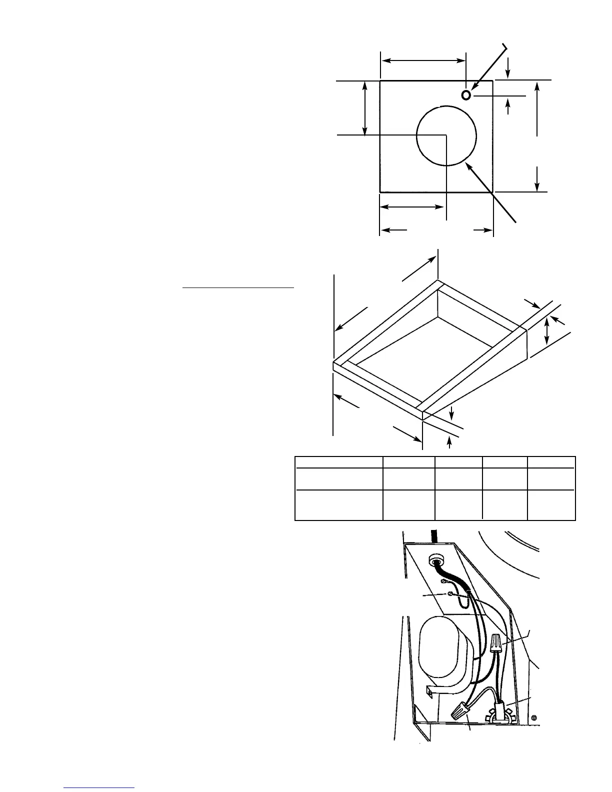
4. From the outside, use the guide hole as a starting
point to lay out the installation.
A. Use a T-square to measure 9
13
/16” (24.9 cm) to
the left of the guide hole, then 12
11
/16”
(32.2
cm) to locate the top-left corner of the layout.
B. Starting from the top-left corner, mark the
rectangular cutout and r
emove only the shingles
in this area.
5. Mark an 11” (27.9 cm) diameter hole centered on
the guide hole. Mark the center of the 1
1
/4” (3.2
cm) diameter electrical wiring hole.
6. Cut out the roof board(s) along the 11” (27.9 cm)
diameter circle and drill a 1
1
/4” hole as marked.
7. For flat roof installations, build a curb that will
mount the blower at a minimum pitch of 2/12.
Discharge end of the blower should be pointed
away from prevailing winds.
8. Remove roofing nails from the shingles around the
top and sides of the cutout area only. Carefully lift
the shingles to allow the back flashing sheet on the
blower housing to fit under them.
9. Center the blower ring in the 11” (27.9 cm)
diameter hole, making sure that the 1 ¼” (3.2 cm)
diameter electrical wiring hold aligns with the hole
in the wiring box.
10. Attach the blower to the roof with the six screws
provided. It is recommended that the screws be
located inside the blower housing. All six holes in
the back panel must be filled, or any moisture that
may get inside the housing could leak into the
house.
11. Using a good grade of roofing cement, seal all of
the shingles around the housing and flashing sheet
as well as the mounting screw heads.
12. Bring electrical wiring through the hole in the
wiring box and secure it according to local codes.
13. Make the electrical connections with the proper
connector for the type of wiring being used.
Connect white to white, black to black, and the
green or bare wire to green.
14. Replace wiring box cover and screws. Do not
pinch wiring under the cover.
15. Check for free movement of the damper before
installing housing cover and screws.
16. Turn on power and check operation of the blower.
20
1
/2”
(52.1 cm)
BB
12
11
/16”
(32.2 cm)
AA
CC
1
1
/4” (3.2
cm) dia. hole
11” (27.9 cm)
dia. hole
RREEMMOOVVEE
SSHHIINNGGLLEESS
29
1
/2”
(74.9 cm)
DD
2” (5.1 cm)
2” (5.1 cm)
7”
(17.8 cm)
RROOOOFF CCUUTTOOUUTT
Black to
Black
Ground to
grounding
screw
120 VAC
Line In
White
to Blue
AB CD
DEV1200 18” 15” 9 13/16’ 22”
(45.7 cm) (38.1 cm) (24.9 cm) (55.9 cm)
DEV1500 21” 18” 12 5/8” 25”
(53.3 cm) (45.7 cm) (32.1 cm) (63.5 cm)
 Loading...