3
Wiring
IMPORTANT: Electronic devices are susceptible to lightning and power station electrical surges from both the AC
outlet and the telephone line. It is recommended that a surge protector be installed to protect against such surges.
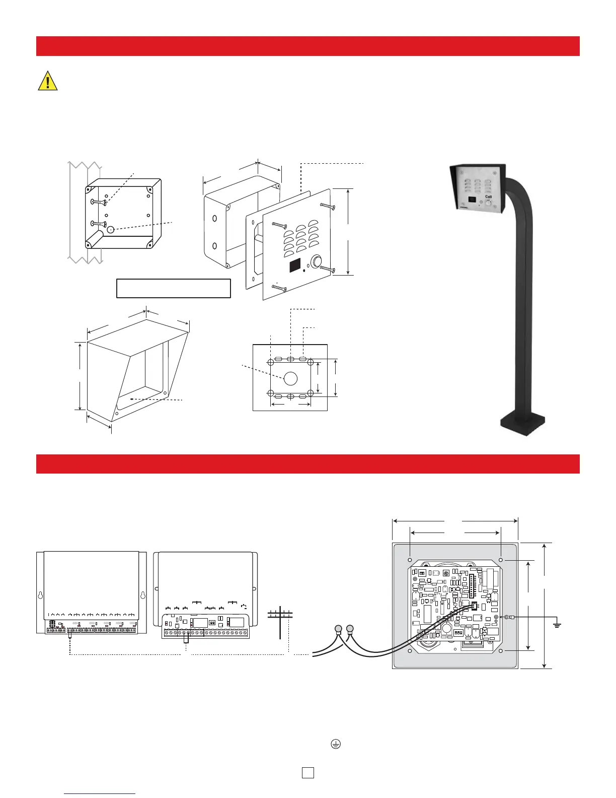
Installation
Optional VE-5x5 Surface
Mount Box (not included)
2.25”
Condensation
Drain Hole
5.14”
5.22”
3.25”
4.0"
Rear View of VE-5x5
(not included)
5.0”
Typical
(2) 0.2 x 0.43 slots for
single gang box
(4) 0.2 x 0.43 slots for
double gang box
(1) 0.74"
diameter
3.0” 3.3”
3.0”
2.1”
Wall Stud
*Plastic Rough-In
Box (included)
VIKING
©
(4) 0.38” diameter
(for gooseneck
pedestal mounting)
Peel paper liner and
adhere gasket to back of
panel, centering over
mounting holes.
Caution: For rough
surfaces (ie: brick, stucco,
etc.) additional caulking
may be required.
Model E-35-EWP shown
in an optional VE-5x5
Surface Mount Box
mounted to a VE-GNP
Gooseneck Pedestal
Other pedestal options
available, see DOD# 424
The optional VE-5x5 Surface Mount Box (left) is
designed to be surface mounted to a single gang
box, double gang box or VE-GNP Gooseneck
Pedestal (shown right). For more information on
the VE-5x5 and VE-GNP, see DOD# 424.
|
OR
|
Wire
knock out
(2) Standard flat head dry wall
(sheet rock) screws (not included)
Important: The E-35 will NOT mount
to a standard double gang box.
* Note: The plastic rough-in box (part # 259576)
may be purchased separately in advance. Go to
www.vikingelectronics.com and click “Spare Parts”.
Call
Caution: When warm air comes in contact with cold surfaces, such as outside walls and conduits, it causes condensation. To prevent condensation from accumulating
inside the E-35 always bring conduit into the bottom of the unit. If this is not possible, drill a 1/4” diameter hole in the bottom of the gray plastic box..
*** Note: To increase surge protection, loosen the PCB mounting screw labeled (as shown above) and fasten a wire with spade terminal (included)
from the mounting screw to Earth Ground (grounding rod, water pipe, etc.)
** Note: The gel-filled (water-tight) butt connectors are designed for insulation displacement on 19-26 gauge wire with a maximum insulation of 0.082
inches. Cut off bare wire ends prior to terminating.
* Note: When installing a line powered phone on a low voltage and/or low loop current phone system extension, a TBB-1B Talk Battery Booster may be
required, see DOD# 632 for more information.
1
2
ON
1
3
2
ON
1
2
ON
Rear View of
the E-35
** Gel-Filled
Butt Connectors
Red (Ring)
Green (Tip)
5.0”
3.63”
5.0”
3.63”
Ring
Terminal
(included)
*** Earth
Ground
(optional)
LED3
LED1 LED2
LED4
LED5
LED6
LED7
C
CCCC
C C
J11-
1
2
3
J10-
12
3
J9-
1
2
3
J8-
1
2
3
J7-
1
2
3
on
VIKING
©
MODEL C-2000B
VIKING
ELECTRONICS
HUDSON, WI 54016
ADVANCED DOOR/GATE AND
ENTRY PHONE CONTROLLER
1 2 3 4 5 6 7
89
10 1 1 12 13 15 16 17 18 19 20 21 22 23 24 25 26 27 28 29 30 31 32
PWR 13.8 VAC
EARTH GND
ENTRY PHONE 1
DOOR STRIKE 1
ENTRY PHONE 2
DOOR STRIKE 2
ENTRY PHONE 3
DOOR STRIKE 3
ENTRY PHONE 4
DOOR STRIKE 4
DOORBELL SWITCH /
AUX. INPUT
AUX. CONTACT
OUTPUT
PHONE LINE
INPUT
LINE OUT
TO PHONES
ANALOG STATION
INPUT
or
* C.O. Line
or Analog
PABX/KSU
Station
Optional C-2000B Advanced Door
Entry Controller, DOD# 156
(not included)
Optional C-200 or C-250 Basic
Single Entry Phone Interface,
DOD# 169 or 172 (not included)
VIKING©
VIKING
ELECTRONICS
HUDSON,
WI
54016
ADVANCED 2 DOOR ENTRY PHONE
CONTROLLER WITH CALL FORWARDING
POWER 13.8V AC
MODEL C-500
PHONE LINE
INPUT
LINE OUT
TO PHONES
1234
ENTRY
PHONE 1
56 789
DOOR
STRIKE 1
N.C.
N.O.
COM
ENTRY
PHONE 2
13 14
SLP
CONTROL
18
+
19
TRIGGER
INPUT 1
10 11 12
TRIGGER
INPUT 2
15 16 17
DOOR
STRIKE 2
N.C.
N.O.
COM
or
A. Wiring the E-35 Phone Board
 Loading...