14
WATER & DRAIN INSTALLATION
The recommended water supply tubing is 1/4” OD copper. Stainless steel flex or reinforced PVC tube may also be
used. Install an easily accessible shut-off valve between the supply and the unit. This shut-off valve should not be
installed behind the unit.
Note: DO NOT use self-piercing type valves.
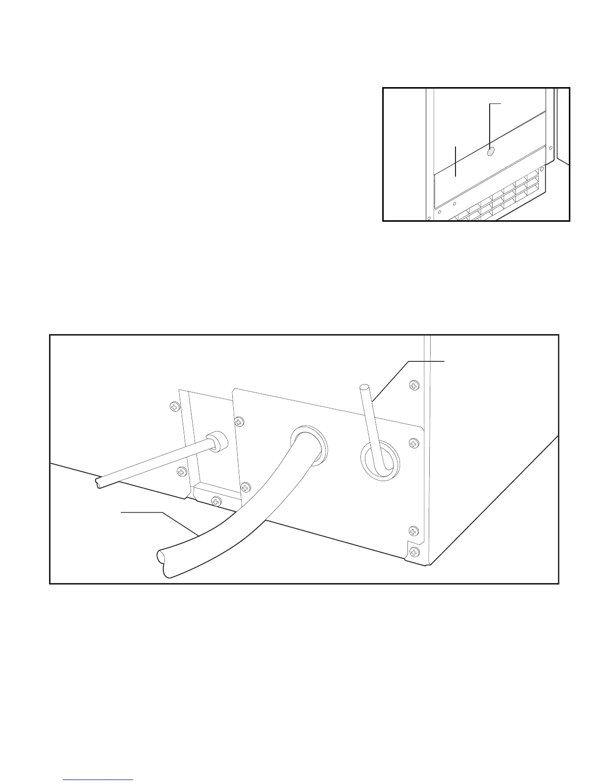
1. Remove the front service access panel by removing the screw.
2. Route the tubing through the right hole in the back to the inlet water
solenoid valve inlet.
3. Install a compression fitting on the tubing and connect to the inlet of the
solenoid (fitting is located in cloth bag behind access panel).
DRAINS
There are two types of ice machine models, one that drains by gravity and
one that has an internal drain pump.
Drain Pump Model drain installation
1. Locate the coil of 3/8” ID plastic drain tubing secured to the back of the unit.
2. Route the plastic drain tube from the back of the unit to the drain connection point.
IMPORTANT NOTE: Often an air gap is required by local codes between the ice maker drain tube and the drain
receptacle.