TECHNICAL DATA
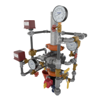
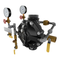
2” MODEL G-2000 DRY VALVE
RISER ASSEMBLY
Page 1 of 13
The Viking Corporation, 210 N Industrial Park Drive, Hastings MI 49058
Telephone: 269-945-9501 Technical Services: 877-384-5464 Fax: 269-818-1680 Email: techsvcs@vikingcorp.com
Visit the Viking website for the latest edition of this technical data page www.vikinggroupinc.com.
Form No. F_011110 17.04.27 Rev 17.1
1. DESCRIPTION
The Viking 2” Model G-2000 Dry Valve Riser Assembly consists of a small prole, light
weight, pilot operated valve that is used to separate the water supply from the dry
sprinkler piping, which is pressurized with air. The pilot operated valve combines an
internal diaphragm assembly that is pressurized closed with priming water, an internal
check valve to isolate the sprinkler system piping, and the Model A-1 Differential Valve
located on the valve trim that allows the valve to operate upon loss of air pressure.
The differential design of the differential valve allows an air supply of moderate pres-
sure to control a higher water supply pressure. When the air pressure in the dry pipe
system is reduced sufciently upon the differential valve due to a sprinkler head op-
eration to destroy the pressure differential, the differential valve will open and relieve
the priming pressure from the internal diaphragm assembly. The internal diaphragm
assembly will compress, allowing water to pass through the body of the valve and cen-
ter of the internal check valve, entering the sprinkler system piping. The Viking Model
G-2000 Valve is designed to be used with a water ow pressure switch and/or water
motor gong. For systems that require an accelerator to increase the speed of water
delivery, the Viking Model E-1 Accelerator shall be used.
2. LISTING AND APPROVALS
cULus Listed: VPZV
FM Approved: Dry Pipe Valves
3. TECHNICAL DATA
Specifications:
Pressure Rating: 250 psi (17.2 Bar) Water Working Pressure
Factory Hydrostatically Tested to: 500 psi
Air to water differential: Approximately 5.75 to 1
Friction Loss (Given in feet of Schedule 40 pipe based on Hazen & Williams formula C = 120):
G-2000 Dry Valve - 8.5’
10” Section of Pipe - 1’
Water Supply Control Valve: 1.9’
G-2000 Dry Valve C
v
Factor: 115.6
Valve Color: Black
Material Specifications: Refer to Figure 11.
Ordering Information:
Available since 2010
Part Number: G-2000 Dry Valve Riser Assembly (See Figure 8) - 16149-1
Shipping Weight: 78 lbs (36 kg)
Accessories:
Model E-1 Accelerator: 08055
Drain Manifold: 16211 (See Figure 9)
Model LD-1 Anti-Column Device: 14800
4. INSTALLATION:
A. General Installation Instructions
1. For proper operation and approval, the valve must be installed in the vertical position as trimmed from the factory. DO NOT
modify the factory assembled trim except as described in this technical data page.
2. Viking recommends installing a 10” section of pipe directly above the dry pipe valve. Prior to valve maintenance, this section
of pipe may be removed to provide clearance for lifting the cover from the body.
3. The dry valve must be installed in an area not subject to freezing temperatures or physical damage. If required, provide a
valve house (enclosure) with adequate heat around the dry valve and trim. Freezing temperatures and/or excessive pressure
will damage the dry valve. When corrosive atmospheres and/or contaminated water supplies are present, it is the owner’s
responsibility to verify compatibility with the Model G-2000 Dry Valve and associated equipment.
4. The Viking Model E-1 Accelerator should be installed at the location indicated in Figure 1 when required by the installation
standard or local Authority Having Jurisdiction.
5. The optional Model LD-1 Anti-Column Device may be installed to prevent water accumulation above the dry pipe valve.
6. The prime line connection shall be made upstream of the water supply control valve using 1/2” or larger pipe.
Replaces page 137a-m, dated January 6, 2012.
(Revised figures 1, 6, 7, 9 and 10)
Q = C
v
√
∆P
S
Q = Flow
C
v
= Flow Factor (GPM/1 psi ∆P)
∆P = Pressure Loss through Valve
S = Specic Gravity of Fluid