0478 111 9930 A - EN
48
8.1 General
● Place the machine on level and firm
ground when performing all the
operations described.
8.2 Assembling the handlebar
Fitting the handlebar sleeves:
● Fit protective sleeves (I) onto
handlebar (1). Position the square hole
on the inner side of the handlebar, the
bores in the handlebar and the square
hole in the handlebar sleeve must be
aligned.
Assembling the handlebar:
● Fit handlebar (1) onto both lower
handlebar sections (2).
● Insert flat head bolts (G) through bores
from the inside to the outside and
tighten with rotary handles (H).
MB 545, MB 545 T,
MB545V, MB545VM,
MB 545 VR:
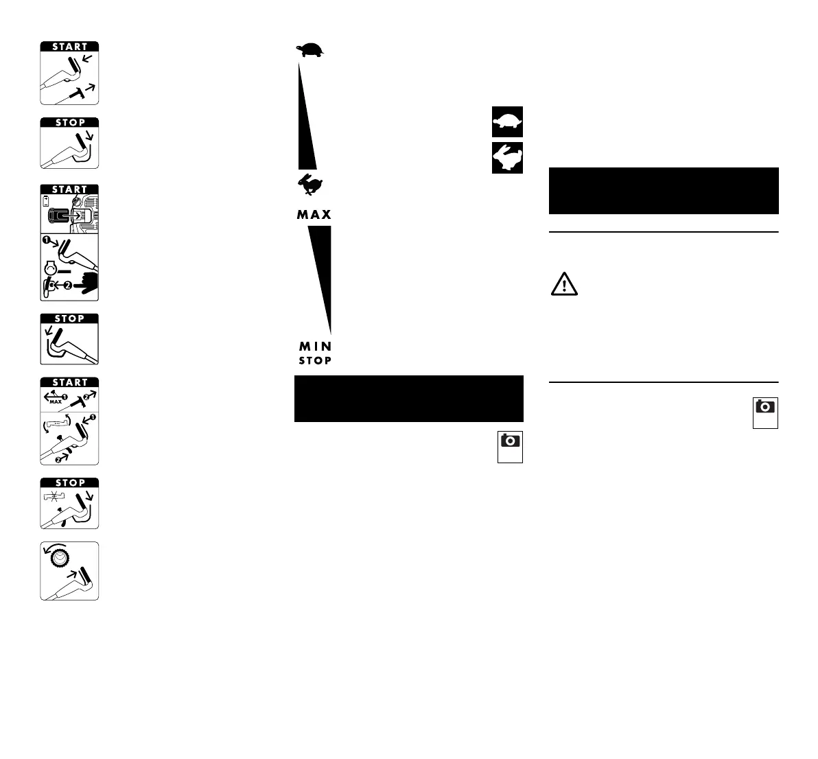
Starting the engine
MB 545, MB 545 T,
MB545V, MB545VM,
MB 545 VR:
Stopping the engine
MB 545 VE:
Inserting the battery, starting
the engine
MB 545 VE:
Stopping the engine
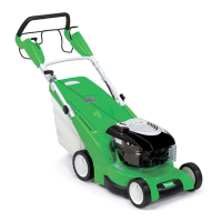
MB 545 VS:
Setting the throttle lever to
the MAX position, starting
the engine, engaging the
mowing blade
MB 545 VS:
Disengaging the mowing
blade
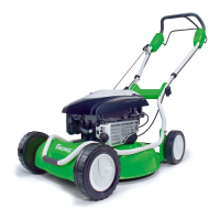
MB 545, MB 545 V,
MB 545 VE, MB 545 VM,
MB 545 VR, MB 545 VS:
Switching on self-propulsion
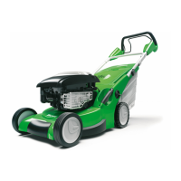
MB 545 V, MB 545 VE,
MB 545 VM, MB 545 VR,
MB 545 VS:
Setting the driving speed
Slow – push Vario
drive lever forwards
Fast – pull Vario
drive lever rearwards
MB 545 VS:
Throttle setting
MAX – maximum speed
MIN – minimum speed
STOP – stop engine
7. Standard equipment
Item Designation Qty.
A Basic unit 1
B Lower part of grass catcher
box
1
C Upper part of grass catcher
box
1
D Pin 2
E Cable guide
(MB 545, MB 545 T
2
1)
F Anti-kink cable protection
(MB 545, MB 545 T
2
1)
G Flat head bolt 2
H Rotary handle 2
2
I Handlebar sleeve 2
J Battery (MB 545 VE) 1
K Charger (MB 545 VE) 1
– Instruction manual 1
–Engine
instruction manual
1
8. Preparing the machine for
operation
Risk of injury!
Observe the safety instructions in
the section "For your safety" (Ö 5.).
Item Designation Qty.
3
 Loading...