EasyManua.ls Logo

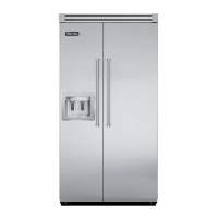
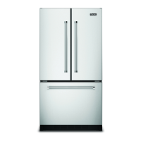
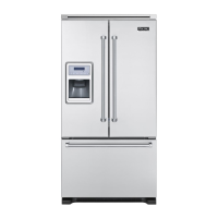
Viking VCBB360R User Manual

Viking VCBB360R
56 pages
To Next Page IconTo Next Page
Page #1 background imageLoading...
Page #1 background image
SERVICE NOTEBOOK
REFRIGERATOR
VCBB360R / VCBB362R (Right) – VCBB360L / VCBB362L (Left)
VIKING RANGE CORPORATION, P.O. DRAWER 956, GREENWOOD, MS. 38930 - USA

Questions and Answers:

Viking VCBB360R Specifications

General IconGeneral
BrandViking
ModelVCBB360R
CategoryRefrigerator
LanguageEnglish

Summary

Technical Information and Safety Warnings

Electrical Safety Warning

Safety warning about electrical shock and proper servicing procedures.

Temperature Relationship Test Chart

Provides test data relating ambient conditions to various temperature and pressure readings.

Display Panel User Operations

Panel Activation, Temperature, and Mode Settings

Covers panel activation, temperature adjustments, and special modes like Max Ref/Frz.

Alarm Handling and Display Off

Explains how to manage alarms and turn off the control panel display.

Electronic System Overview

Power and Showroom Switch Functions

Describes the function and location of power disconnect and showroom switches.

Alarm System Functions

Details the Power Up Alarm and Door Open Alarm functions and their behavior.

Temperature Control System

Thermistor Resistance Specifications

Table showing resistance values for freezer and refrigerator thermistors at various temperatures.

Thermistor Operation Logic

Explains how thermistor resistance affects compressor, fan, and control operations.

Adaptive Defrost System

Defrost Cycle Adaptation Logic

Explains how compressor run time influences defrost cycle frequency and duration.

Vacation Mode and Defrost Dwell Time

Details Vacation Mode requirements and dwell time after defrost.

Advanced Control Programming

Program Mode Access and Navigation

Instructions for entering and switching between Program Modes A and B.

Displaying Temperature Readings

How to display refrigerator and freezer thermistor temperatures in BCD format.

Program Mode B Functionality

Introduces advanced settings available in Program Mode B.

Keyboard and Alarm Delay Configuration

Configuration of keyboard behavior and door alarm delay duration.

Max Refrigerator Run Time Setting

How to adjust the maximum run time for the refrigerator cooling mode.

Program Mode Advanced Settings

Max Freezer Run Time and Temp Offset

Adjusting freezer run time and calibrating temperature offsets.

Defrost Mode and Compressor Start Control

Selecting defrost mode and forcing compressor start.

Exiting Program Mode Safely

Procedures for saving changes and exiting program mode.

System Electronic Testing

Forced Defrost and Compressor Start Procedures

Procedures for initiating forced defrost and compressor start cycles.

Thermistor and Evaporator Fan Testing

How to test thermistor circuits and evaporator fan operation.

Electronic Control Board Description

High Voltage Control Board Wiring Schematic

Detailed wiring diagram of the main control board and its components.

High Voltage Board Component Checks

Low Voltage Board and Motor Input Checks

Specifies voltage checks for low voltage board and motor operations.

Defrost and Fan Component Voltage Tests

Details voltage checks for defrost heater, relay, terminator, and fans.

Full System Wiring Diagram

Wiring Connections and Component Layout

Illustrates the physical wiring layout and connections for various components.

Electrical System Wiring Schematic

Detailed Electrical Circuit Overview

Provides a detailed schematic of the refrigerator's electrical circuits.

Freezer Compartment Operation Theory

Freezer Thermistor and Control Logic

Explains how thermistor resistance affects freezer compartment cooling and fan operation.

Refrigeration Compartment Operation Theory

Refrigeration Thermistor and Fan Control

Details how thermistor changes affect fresh food fan and condensate evaporator fan operation.

Compartment Operation Interplay

Combined Thermistor and Fan Control Logic

Explains how both thermistors influence compressor and fan operations.

Adaptive Defrost System Theory

Defrost Relay and Heater Control Mechanism

Describes how the electronic control signals the defrost relay and heater.

Component Specifications Overview

Electrical and Mechanical Component Specs

Lists specifications for bulbs, capacitors, compressors, and driers.

Heater and Circuit Board Specs

Details specifications for mullion heaters, high/low voltage boards.

Component Specifications - Motors, Relays, Switches

Motor, Overload, and Relay Specs

Provides specifications for various motors, overload protectors, and relays.

Switch Specs and Wiring Details

Details specifications for keyboard switches and refrigerator light switches.

Component Specifications - Thermistors, Valves

Switch, Thermistor, Thermostat, Valve Specs

Lists specifications for various switches, thermistors, thermostats, and water valves.

Component Testing Procedures

Capacitor Testing Guide

Step-by-step guide for testing the run capacitor's functionality.

Capillary Tube Function and Restriction Testing

Explains capillary tube purpose and how to identify restrictions.

Component Testing - Compressor

Compressor Testing: Resistance, Ground, Operation

Detailed procedures for testing compressor resistance, ground, and operation.

Component Testing - Condenser

Condenser Functionality and Leak Detection

Explains condenser operation and methods for detecting refrigerant leaks.

Component Testing - Drier, Evaporator

Drier Replacement and Evaporator Leak Tests

Procedures for drier replacement and evaporator leak detection.

Component Testing - Heaters, Icemaker, Motors

Heater, Icemaker, Motor Testing Procedures

Procedures for testing cavity heaters, icemaker components, and motors.

Component Testing - Relays, Motors

DC Motor, Overload, Relay Testing

Steps for testing DC motors, overload protectors, and PTC relays.

Component Testing - Switches

Switch Testing: Keyboard, NO/NC, Power

Procedures for testing various types of switches.

Component Testing - Thermistors, Valves

Showroom Switch, Thermistor, Thermostat, Valve Tests

Testing procedures for showroom switches, thermistors, thermostats, and water valves.

Troubleshooting Common Issues

Unit Non-Operation and Temperature Problems

Addresses problems like no power, unit not running, and section temperature deviations.

Troubleshooting Operational Issues

Continuous Run, Noise, Frost, and Cycling Issues

Covers continuous operation, noisy operation, frost on evaporator, and frequent cycling.

System Performance Diagnosis

Pressure-Temperature Relationship Chart

Details how various conditions affect system pressures and temperatures.

Service Procedures Introduction

Service Equipment and Refrigerant Safety

Lists necessary tools and safety precautions for refrigerant handling.

Service Procedures - System Integrity

System Dehydration, Leak Testing, Restrictions

Procedures for dehydrating, leak testing, and identifying system restrictions.

Service Procedures - System Maintenance

Restriction Testing, Evacuation, and Charging

Continues restriction testing and covers system evacuation and charging.

Service Procedures - Refrigerant Handling

Evacuation, Charging, HFC134a Handling

Detailed steps for evacuation, charging, and specific HFC134a handling guidelines.

Service Procedures - Refrigerant and Compressor

HFC134a Info and Compressor Testing

Covers HFC134a properties, comparisons, and compressor testing procedures.

Service Procedures - Mechanical Adjustments

Compressor Replacement, Brazing, Adjustments

Procedures for replacing compressors, brazing, and adjusting door stops/hinges.

Refrigerant Flow Path

Refrigerant Circuit Diagram

Illustrates the path of refrigerant through the system components.

Cabinet Airflow Patterns

Internal Air Circulation Paths

Diagram showing how air is circulated within the refrigerator and freezer compartments.

Machine Compartment Airflow

Compressor and Condenser Airflow Paths

Diagram illustrating airflow in the machine compartment around the compressor and condenser.

External Condensation Patterns

Condensation Classification and Test Conditions

Explains condensation levels and test conditions for external sweating.

Disassembly Steps - Doors and Cabinets

Door, Drawer, Switch, Fan Removal

Steps for disassembling doors, drawers, switches, and fans.

Evaporator, Thermostat, Heater Removal

Procedures for removing evaporator covers, thermostats, and heaters.

Disassembly Steps - Evaporators and Components

Evaporator, Fan, Grille Disassembly

Steps for removing evaporator, fan components, toe grille, and rollers.

Cabinet Components and Access Panel Removal

Procedures for removing condensate fan, shelf supports, pantry assembly, and accessing boards.

Disassembly Steps - Boards, Compressors, Condensers

Board, Compressor, Condenser Removal

Steps for removing high voltage boards, compressor, condenser, and related parts.

Capacitor, Overload, Fan, Switch Removal

Procedures for removing capacitors, overloads, fans, and switches.

Icemaker System Overview

Icemaker Specs and Operation

Details icemaker components, operational principles, and test point identification.

Icemaker Testing and Verification

Steps for testing icemaker power, thermostat, and motor.

Icemaker Module and Support Assembly

Module Checks and Support Disassembly

Procedures for checking module ohmmeter readings and disassembling support assembly.

Shut-Off Arm and Fill Cup Procedures

Instructions for handling the shut-off arm and installing the fill cup.

Icemaker Ejector and Control Mechanisms

Ejector Blades and Control Box Access

Procedures for installing ejector blades and accessing the control box.

Water Fill Adjustment and Timing

Explains how to adjust water fill volume and its relation to timing.

Icemaker Thermostat and Wiring Harness

Thermostat Replacement and Harness Removal

Steps for replacing the icemaker thermostat and removing the wiring harness.

Icemaker Water Valve and Harness Details

Water Valve Functionality and Wire Harness

Details the water valve operation and the wire harness with its thermal fuse.

Icemaker Troubleshooting Guide - Part 1

Troubleshooting: No Ice, Low Ice, 2:30 Ejector

Addresses issues like no ice production and problems at the 2:30 ejector position.

Icemaker Troubleshooting Guide - Part 2

Troubleshooting: Various Ejector Positions

Covers troubleshooting for specific ejector positions (3:00, 4:00, 6:00, 7:30, 9:00).

Icemaker Troubleshooting Guide - Part 3

Troubleshooting: Excessive Ice, Hollow Cubes, Flooding

Addresses excessive ice production, hollow cubes, and flooding problems.

Icemaker Wiring Diagram and Parts

Icemaker Wiring and Component Layout

Visual representation of the icemaker's wiring and the layout of its parts.

Related product manuals