T
Travis AvilaAug 15, 2025
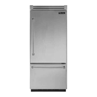
What to do if Viking VCBB536 Refrigerator is too warm?
- GGary PerezAug 15, 2025
If your Viking Refrigerator is too warm, consider the following: * Minimize how often you open the door. * Allow temperatures to stabilize after placing warm food inside. * Adjust the control to a medium setting. * Check the door seal for proper closure and replace it if needed. * Make sure airflow isn't obstructed. * Verify the refrigerator fan's operation.