47
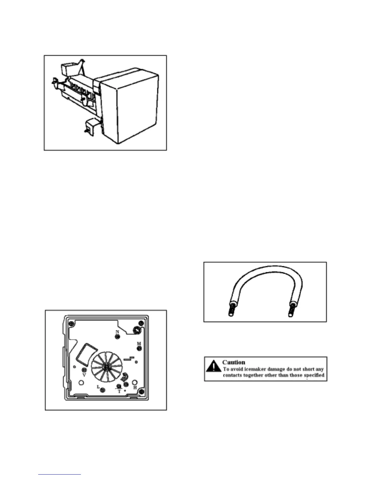
ICEMAKER
Operation
Thermostat closes when temperature reaches 17° ±
3°F (-8.3° ± 1.5C). current flows through thermostat
to motor. See “Icemaker Wiring Diagram”. Motor is
linked with drive gear. From module, there are
copper contacts that ride on copper strips on backside
of drive gear. As the drive gear rotates, contacts will
make or break a circuit (track) to the copper strips to
operate icemaker.
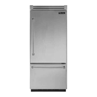
All components can be tested without removing
icemaker or moving refrigerator away from
installation. Remove cover. Test points are
identified on Module.
N=Neutral side of line
M=Motor connection
H=Heater connection
T=Thermostat connection
L=L1 side of line
V= Water valve connection
Specifications
Mold Heater 185 watts, 264 ohms
Thermostat Close 17° ± 3°F (-8° ± 1°C)
(Bimetal) Open 32° ± 3°F (0° ± 1°C)
Water Fill 140cc, 7.5 seconds
Motor Cycle Stamped in circuit.
Plug in connectors
One revolution of blades takes
3 minutes plug stall time on ice
(eject and water fill).
Test Procedures
Verify icemaker has power, shut-off arm is down,
and freezer is cold enough to close bimetal
thermostat.
• Test point L and N will verify 120 volts to
icemaker module.
• Test point T and H will verify bimetal thermostat
is open or closed.
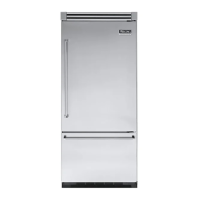
• Verify test probe go into test point ½” (1.25cm)
1. Short T and H with shunt (insulated 14 gauge
wire with ends stripped back 5/8” (1.6cm) to run
motor. If motor runs, replace bimetal thermostat.
If motor does not run, replace module.