Diagnostic Information
12 SMR-0003 © Viking Range Corporation
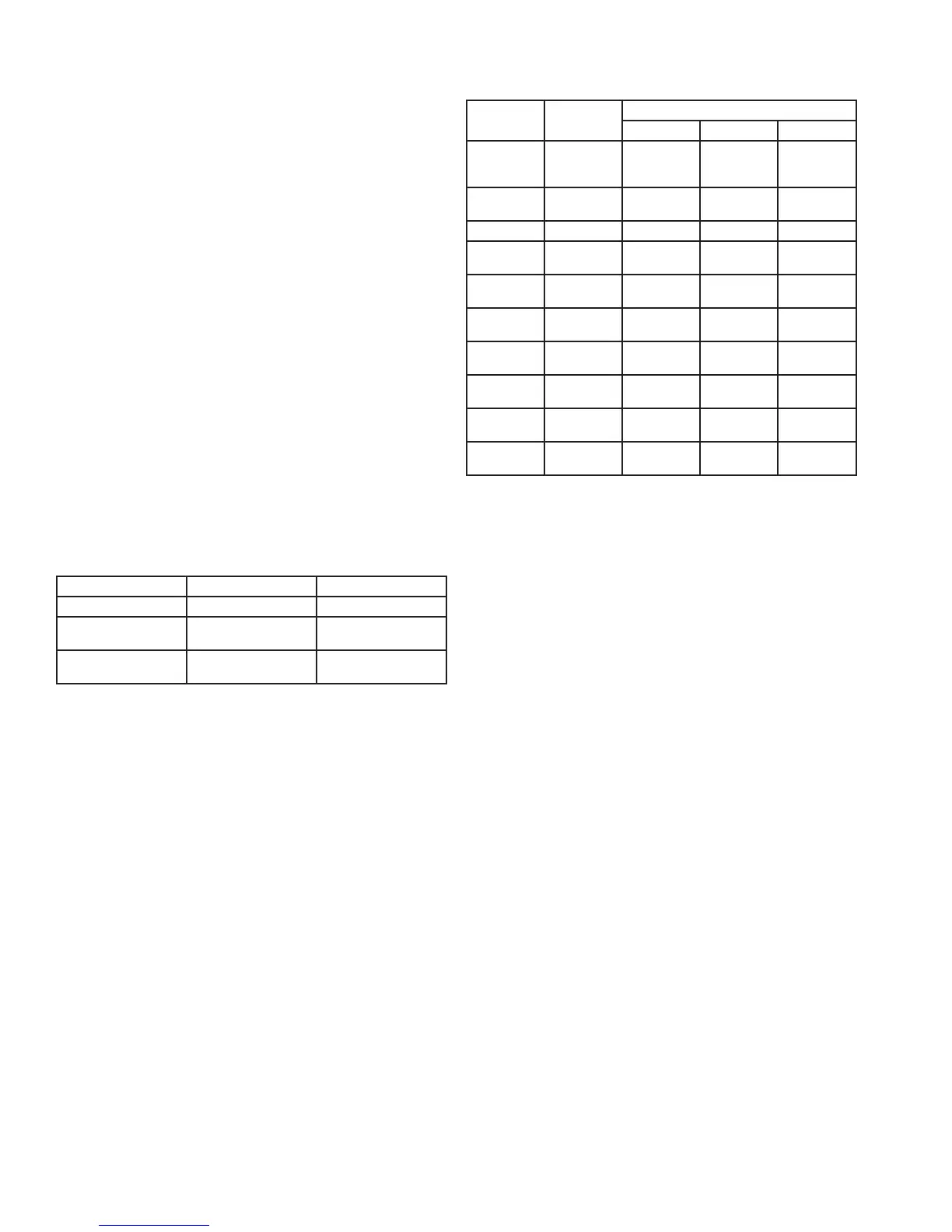
Available Component Tests
Test #
Component
Description
Available Status Indicators
OK Off/Open On/Shorted
0
Temp
Sensor A -
Evaporator
0- 00 01
1
Temp Sensor
B - Display
1- 10 11
2 Compressor n/a 20 21
3
Interior/Ice
Maker Fan
n/a 30 31
4
Reverse Gas
Solenoid
n/a 40 41
5
Condenser
Fan
n/a 50 51
6
Mullion
Heater
n/a 60 61
7
Door A
Sense
n/a 70 71
8
Door B
Sense
n/a 80 81
9
Door C
Sense
n/a 90 91
Note: Must use magnet to change state of door C sense
Disabling Service Mode:
To exit service mode, press and hold the “WARMER”
button while pressing the ”COLDER” button four (4)
times within ve (5) seconds.
Service Mode will automatically disable after ve (5) •
minutes of no keypad entry.
Ordering Parts
The following information will need to be given when
inquiring about service parts:
Model and serial number located on the serial •
nameplate (see Introduction, Serial Nameplate)
Color of the model•
Metal or plastic grille•
Type of door•
To order parts, call or write:
Viking Range Corporation
Customer Service
111 Front Street
Greenwood, Mississippi 38930 USA
662.455.1200
For product information, call 1.888.VIKNG1 (845.4641)
or visit the Viking Web Site at vikingrange.com
Service Diagnostics Mode
Service Diagnostics Mode allows you to identify the
rmware and software versions, test status of “model
specic” system components and sensors, and change
state of components where applicable (i.e. - compressor
on/off, etc...).
Enabling Service Mode:
To enable Service Mode, press and hold the “WARMER”
button while pressing the “COLDER” button four times
within ve seconds.
You cannot enable Service Mode while in Set Mode.•
All system functions will remain in their current state •
while in Service Mode.
Alarms are disabled during Service Mode and reset •
after exiting Service Mode.
Service Mode will automatically disable after ve (5) •
minutes of no keypad entry.
After entering Service Mode, the rst number that you
will see indicates the software model number for the
particular unit you are servicing. For example, if you are
servicing a 24 inch wine cellar (DFUW, DUWC, VUWC),
the rst number you will see is 11. See chart below for
corresponding model and software reference.
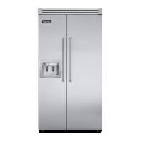
Software Model Number
Model Description Software Model Number
DFUW, DUWC, VUWC 24 inch Wine Cellar 11
DFUR, DUAR, VUAR 24 inch Beverage
Center
21
DFRD, DURD, VURD 24 inch Refrigerated
Drawers
16
The second number you will see indicates the software
version release. For example, if you see 44 on the
display panel it indicates software version 4.4.
Diagnostics:
While in Service Mode, press the “SET” button to step
through Tests 0-9. The rst digit of the display will show
the test number. The second digit indicates the current
state of each component under test and is displayed as
“1” being ON, CLOSED, or SHORTED and “0” being
OFF or OPEN. Tests 0 and 1 reveal an open or shorted
condition detected at the sensor inputs. Tests 2 through
6 allow you to turn loads ON with the “WARMER” button
and OFF with the “COLDER” button. Tests 7 through 9
verify state change of the door switches and/or magnetic
reed sensor. The component tests available are
described in Available Component Tests chart.