4
B2
B1
EXT+
EXT-
VLED
M
PA
CA
M
S+
S-
+12V
-L
SR
F2
F1
M
X
B2
B1
EXT+
EXT-
VLED
M
PA
CA
M
S+
S-
+12V
-L
SR
F2
F1
M
X
CN2
CN1
CS2411 250105
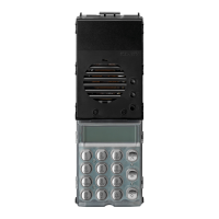
Operazioni preliminari
Negliimpianticonunasolatargal’identificativoIDdeveessereMASTER.
L’unitàelettronicadidefault,vienefornitaconidentificativoID=1(cioè
Master).
Se sono presenti nell’ impianto più targhe, si dovrà definire una targa MA-
STERelealtreSLAVE.Perqueste,dovràessereassegnatol’identifica-
tivoIDcomeunitàelettronicheSLAVE.Ognitargadovràavereunnumero
identificativoIDunivoco.Peraccedereaiponticellidiconfigurazionedovrà
essere sollevata la copertura bianca dei tasti (vedi fig. 3)
Preliminary procedures
Insystemswithasingleentrancepanel,theIDmustbeMASTER.
ThedefaultelectronicunitissuppliedwiththeID=1(i.e.Master).
Ifthereareseveralentrancepanelsinthesystem,aMASTERpanelshould
beestablishedandtheothersdesignatedasSLAVE.Thesemustbeas-
signed
withIDforaSLAVEelectronicunit.Eachentrancepanelmusthave
asingleIDnumber.Toaccesstheconfigurationjumpers,liftthewhitebutton
cover (see fig. 3).
DL3
DL4
DL5
DL6
1
2
3
4
5
6
TP
SV
SA
DL3
DL4
DL5
DL6
1
2
3
4
5
6
SV
TP
SA
PRG
RESET
3
2
1
Per la corrispondenza
della congurazione dei
ponticelli vedi tabella 1
a pagina 5
For jumper congura-
tion correspondence, see
table 1 on page 5.
g. 3
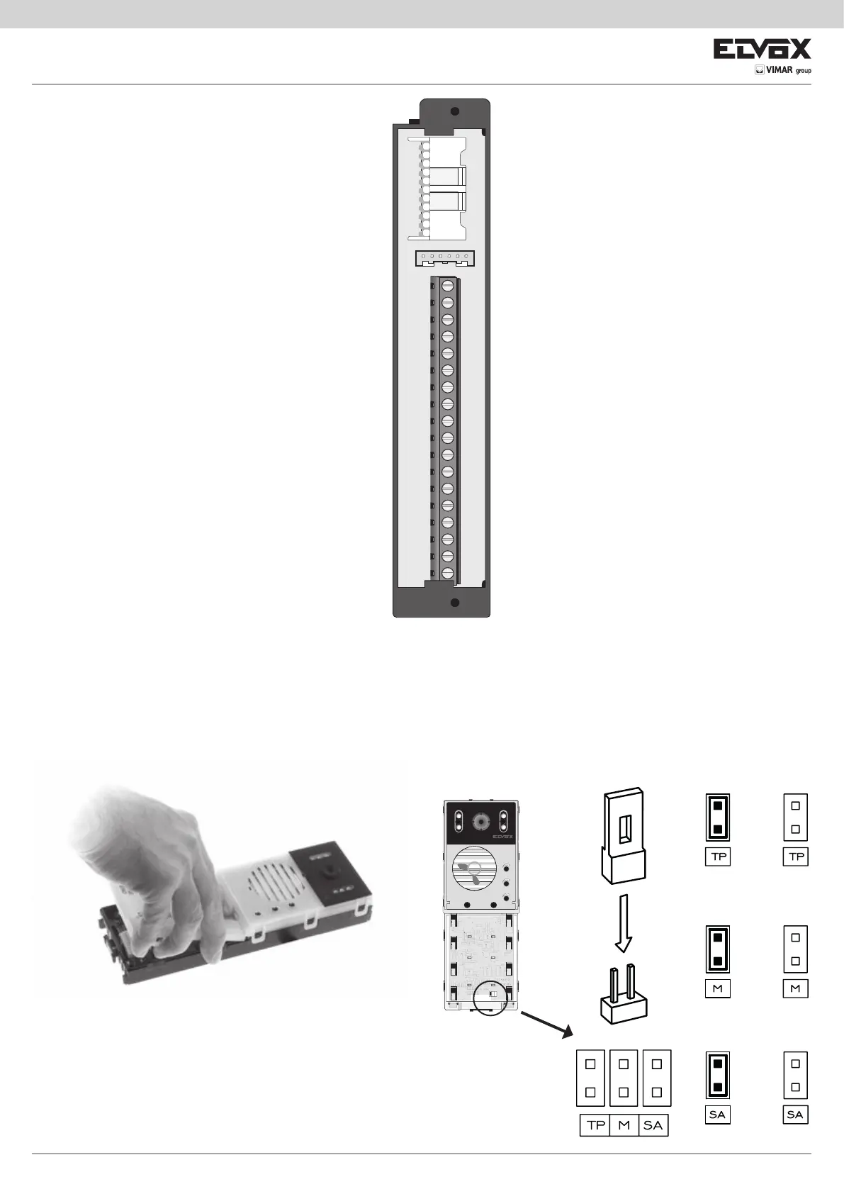
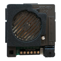
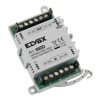
Morsettiera
CN1) Connettore per unità elettronica.
CN2) Connettore per programmatore art. 950C o interfac-
ciaart.692I/Uoart.692I.
B2) Bus (montante).
B1) Bus (montante).
EXT+) Alimentazioneesterna(+art.6923).
EXT-) Alimentazioneesterna(-art.6923)
VLED) AlimentazioneLEDpermodulisupplementari.
X) Ingressovideo(animacoassiale),pertelecamera
esterna (solo con 13F3).
M) Ingressovideo(calzacoassiale),pertelecamera
esterna (solo con 13F3).
PA) Ingressopersensoreportaaperta(conriferimentoal
morsetto M).
CA) Comando apriporta (con riferimento al morsetto M).
M) Massa.
S+) Uscitaserratura12Vcc(+)(vedinotasotto).
S-) Uscitaserratura12Vcc(-)(vedinotasotto).
+12V) Uscita+12V(max120mA)conlimitatoredicor-
rente.
-L) Pilotaggio telecamera esterna, uscita open collector.
SR) Pilotaggioserraturatramiterelè,uscitaopencollec-
tor.
F2) PilotaggiofunzioneF2tramiterelè,uscitaopencol-
lector.
F1) PilotaggiofunzioneF1tramiterelè,uscitaopencol-
lector.
M) Massa.
Nota:usciteS+/S-.LatargafornisceunpiccodicorrenteI
T
> 1A per 10 ms dopo il quale segue una corrente di manteni-
mentoI
M
=200mApertuttaladuratadelcomandoserratura
(vedi tempo serratura).
Terminal block
CN1) Connector for electronic unit.
CN2) Connector for programmer art. 950C or inter-
faceart.692I/Uorart.692I.
B2) Bus (cable riser).
B1) Bus (cable riser).
EXT+) Externalpowersupply(+art.6923).
EXT-) Externalpowersupply(-art.6923).
VLED) LEDpowersupplyforadditionalmodules.
X) Videoinput(coaxialcore),forexternalcamera
(only with 13F3).
M) Videoinput(coaxialsheath)forexternalcam-
era (only with 13F3).
PA) Inputfordooropensensor(withreferenceto
terminal M).
CA) Door open command (with reference to termi-
nal M).
M) Ground.
S+) Lockoutput12Vdc(+)(seenotebelow).
S-) Lockoutput12Vdc(-)(seenotebelow).
+12V) Output+12V(max120mA)withcurrentlimiter.
-L) External camera pilot, open collector output.
SR) Lock pilot via relay, open collector output.
F2) F2 function pilot via relay, open collector out-
put.
F1) F1 function pilot via relay, open collector out-
put.
M) Ground.
Note:S+/S-outputs.Theentrancepanelsuppliesacur-
rentpeakI
T
> 1A for 10 ms after which there follows a
holdingcurrentI
M
=200mAfortheentiredurationofthe
lock command (see lock time).