27
42920.P
Note:
• La lunghezza minima del cavo tra due videocitofoni deve essere 5m.
• Alimentatore multispina: sono presenti due forchette, la rossa deve essere colle
-
gata al morsetto 24V e la nera al morsetto GND del videocitofono.
• Nei sistemi composti da due posti esterni, qualora fosse già attiva una comuni
-
cazione tra posto esterno e videocitofono, in caso di chiamata dall’altro posto
esterno, un segnale di occupato (sequenza di bip) segnalerà la necessità di
attendere che il sistema sia libero.
• Nell'eseguire il collegamento di sistema, si raccomanda di non lasciare termina
-
zioni scollegate dai dispositivi videocitofonici: ogni tratta di cavo non terminata
può essere causa di disturbo.
Schemi di collegamento
Legenda per schemi di collegamento
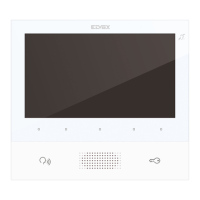
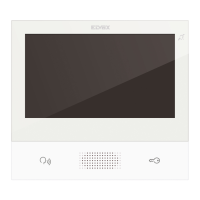
A1 - Videocitofono appartamento 1
A2 - Videocitofono appartamento 2
A3 - Videocitofono appartamento 3
A4 - Videocitofono appartamento 4
A1.2 - Videocitofono supplementare, appartamento 1 - interno 2
A1.3 - Videocitofono supplementare, appartamento 1 - interno 3
B - Alimentatore
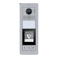
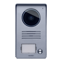
C1 - Posto esterno 1 pulsante
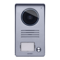
C2 - Posto esterno 2 pulsanti
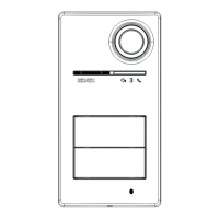
C4 - Posto esterno 4 pulsanti
D - Distributore 42920.D
E - Pulsante supplementare serratura
F - Serratura elettrica
G
H - Alimentatore supplentare
L - Telecamera TVCC supplementare
M - Alimentatore per telecamera TVCC esterna
Notes:
• The minimum cable length between two video entryphones must be 5m.
• Multi-plug power supply unit: two forks are present, the red one should be con
-
nected to the 24V terminal and the black one to the GND terminal of the video
entryphone.
• In systems comprising two outdoor stations, if communication between an out
-
door station and the video entryphone is already under way, in the case of a call
from the other outdoor station, a busy signal (sequence of beeps) will indicate
the need to wait for the system to be free.
• When making the system connection, we advise against leaving terminations
disconnected from the video door entry devices: every cable run without a termi
-
nation could lead to interference.
Wiring diagrams
Key for wiring diagrams
A1 - Apartment 1 video entryphone
A2 - Apartment 2 video entryphone
A3 - Apartment 3 video entryphone
A4 - Apartment 4 video entryphone
A1.2 - Apartment 1 additional video entryphone - indoor 2
A1.3 - Apartment 1 additional video entryphone - indoor 3
B - Power supply unit
C1 - 1 push button outdoor station
C2 - 2 push buttons outdoor station
C4 - 4 push buttons outdoor station
D - Distributor 42920.D
E - Additional lock push button
F - Electrical lock
G - NO/NC contact relay control
H - Additional power supply unit
L - Additional CCTV camera
M - Power supply unit for external CCTV camera
Remarques :
• Le câble entre deux portiers-vidéo doit mesurer au moins 5 m.
• Alimentation multiches : deux fourchettes sont présentes ; brancher la rouge
sur la borne 24 V et la noire sur la borne GND du portier-vidéo.
• Sur les systèmes comprenant deux postes extérieurs, si un poste extérieur est
déjà en communication avec le portier-vidéo, en cas d'appel provenant de l'autre
poste extérieur, un signal occupé (répétition de bips) mettra en attente jusqu'à ce
que le système soit libre.
• En réalisant la connexion du système, ne laisser aucune cosse débranchée des
dispositifs portiers-vidéo : chaque tronçon de câble non branché peut provoquer
des perturbations.
Schémas de connexion
Légende pour schémas de connexion
A1 - Portier-vidéo appartement 1
A2 - Portier-vidéo appartement 2
A3 - Portier-vidéo appartement 3
A4 - Portier-vidéo appartement 4
A1.2 - Portier-vidéo supplémentaire, appartement 1 - poste 2
A1.3 - Portier-vidéo supplémentaire, appartement 1 - poste 3
B - Alimentation
C1 - Poste extérieur 1 poussoir
C2 - Poste extérieur 2 poussoirs
C4 - Poste extérieur 4 poussoirs
D - Distributeur 42920.D
E - Poussoir supplémentaire gâche
F - Gâche électrique
G - Commande relais depuis contact NO/NF
H - Alimentation supplémentaire
L - Caméra CCTV supplémentaire
M - Alimentation pour caméra CCTV extérieure
Hinweis:
• Die min. Kabellänge zwischen zwei Videohaustelefonen beträgt 5m.
• Vielfachstecker-Netzteil: Von den zwei Gabeln muss die rote an die 24 V Klem
-
me und die schwarze an die GND-Klemme des Videohaustelefons angeschlos-
sen werden.
• Falls in Systemen mit Außenstellen bereits eine Kommunikation zwischen
Außenstelle und Videohaustelefon ablaufen sollte, meldet beim Ruf von der
anderen Außenstelle ein Besetzt-Zeichen (Sequenz von Pieptönen), dass auf
die Freigabe des Systems gewartet werden muss.
• Bei Herstellung des Systemanschlusses sollten Terminierungen der Video
-
sprechgeräte nicht abgetrennt werden: unterminierte Kabelabschnitte Störun-
gen verursachen.
Anschlusspläne
Beschriftung für Schaltpläne
A1 - Videohaustelefon Wohnung 1
A2 - Videohaustelefon Wohnung 2
A3 - Videohaustelefon Wohnung 3
A4 - Videohaustelefon Wohnung 4
A1.2 - Zusätzliches Videohaustelefon, Wohnung 1 - Innenstelle 2
A1.3 - Zusätzliches Videohaustelefon, Wohnung 1 - Innenstelle 3
B - Netzteil
C1 - Außenstelle 1 Taste
C2 - Außenstelle 2 Tasten
C4 - Außenstelle 4 Tasten
D - Verteiler 42920.D
E
F - Elektroschloss
G - Relaissteuerung über NO/NC-Kontakt
H - Zusatznetzteil
L - Zusätzliche Videoüberwachungskamera
M - Netzteil für Außen-Videoüberwachungskamera
 Loading...