19
Contents
Previous
Page
First
Page
Next
Page
Previous
View
Configuration
16 The encoders in the Vision 250 E/IT head should be configured using the software to which the head is
connected.
17 Jumpers in the IT interface box must be set to suit the type of RS interface. Proceed as follows:
17.1 Disconnect the mains power supply.
17.2 Remove the six screws securing the lid of the box.
17.3 Identify the jumpers (29) and set them in the positions indicated in Fig 2.2.
17.4 Replace the lid and secure with six screws.
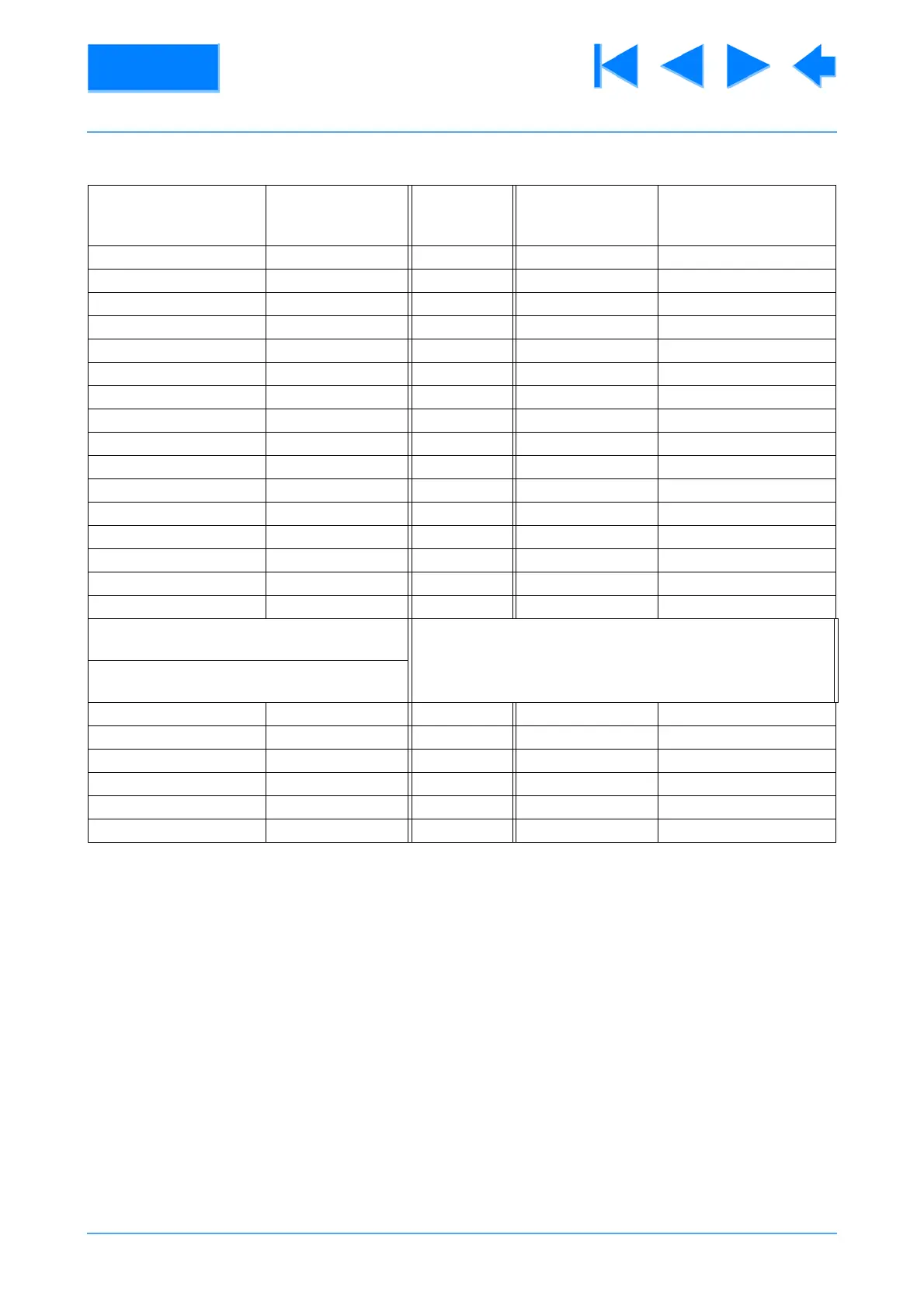
Table 2.3 250 IT Encoder Cable Pin Designations
Encoder Connector
Pin No.
Wire
Colour
Function Wire
Colour
IT interface box
Connector
Pin No.
1 Black/White Gnd Black/White 8
2 White/Black +5 White/Black 7
5 White/Green PB- White/Green 6
6 White/Brown PA - White/Brown 4
7 Black/White Gnd Black/White 8
8 White/Black +5 White/Black 7
11 Green/White PB+ Green/White 5
12 Brown/White PA + Brown/White 3
13 Black/White Gnd Black/White 8
14 White/Black +5 White/Black 7
17 White/Grey TB- White/Grey 12
18 White/Orange TA- White/Orange 10
19 Black/White Gnd Black/White 8
20 White/Black +5 White/Black 7
23 Grey/White TA+ Grey/White 11
24 Orange/White TB+ Orange/White 9
Pins 1, 7, 13 and 19 are jumped together
Pins 2, 8, 14 and 20 are jumped together
Lens Connector
Pin No.
1 Red/White +5 Red/Orange 19
2 Red/Black ZA+ Red/Green 15
3 Green ZB+ Green/Red 17
5 Red FA+ Red/Black 21
6 Blue FB+ Black/Red 23
9 Orange Gnd Orange/Red 20