20
Contents
Previous
Page
First
Page
Next
Page
Previous
View
Balancing the head
18 Balancing the Vision 250 E/IT head achieves two objectives. Firstly, when a head is correctly balanced
the operator will need a minimum amount of even effort to move the head. Secondly, once balanced, the head
and its payload can be set to any tilt position and the head will maintain this position with ‘hands off’.
19 The graph (Fig 2.3) illustrates the relationship between load and centre-of-gravity (C of G) height and
may be used to ascertain the suitability of the head for any given combination of camera, lens and
accessories. The shaded area of the graph corresponds to those loads/C of G heights that can be balanced
over the full tilt range. The areas to the right indicate the progressively reducing tilt range over which the head
can balance higher loads.
20 Prior to balancing the head ensure that the pan bars and any ancillary equipment have been fitted and
the encoders connected in order to prevent upsetting the balance once it has been achieved.
21 Balance the head as follows:
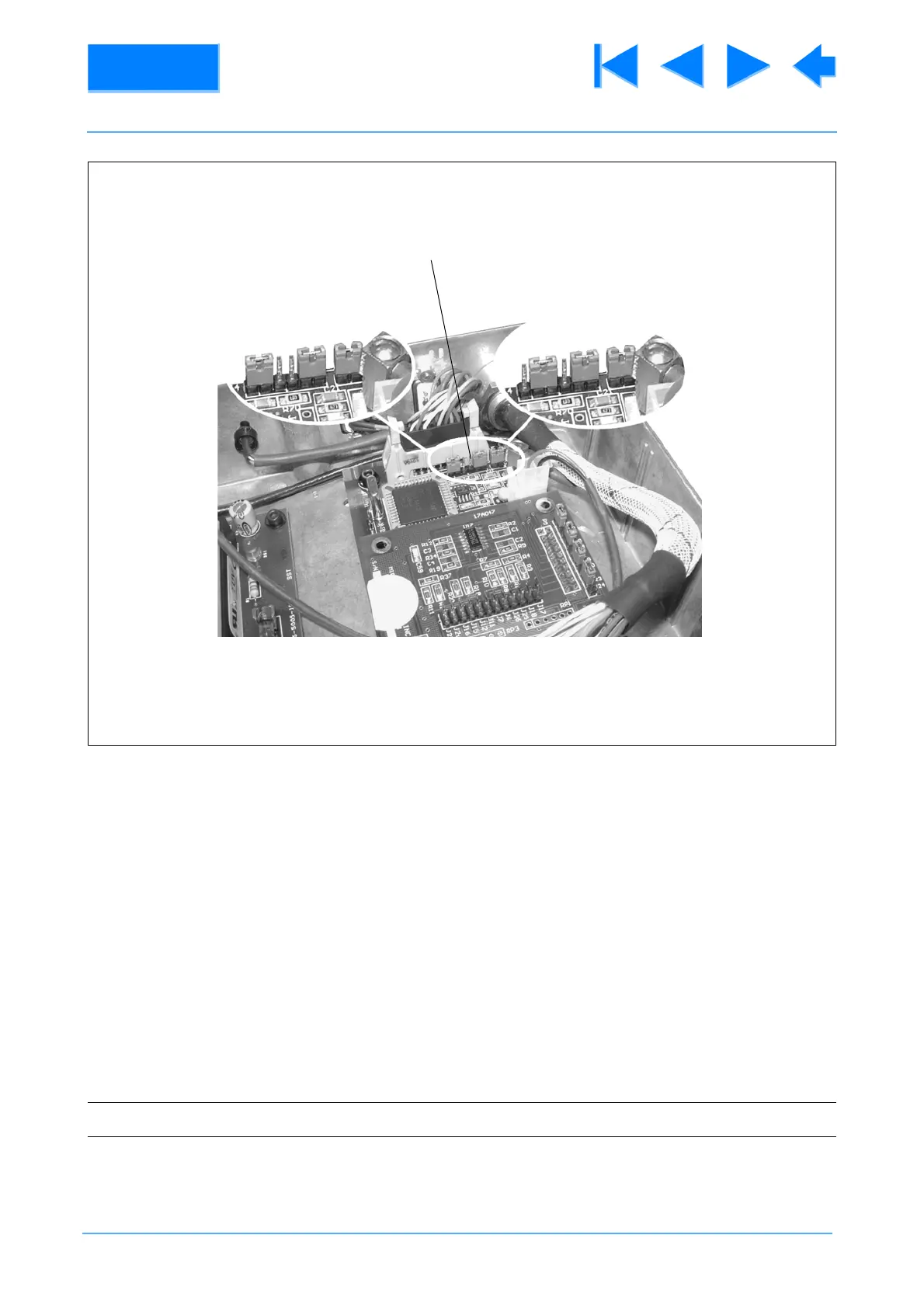
Fig 2.2 IT Interface Box Configuration
NOTE: Be prepared to prevent the head falling away suddenly
RS-232 RS-422
(29)