18
Contents
Previous
Page
First
Page
Next
Page
Previous
View
Connecting the head
250 E
13 The Vision 250 E is supplied with an unwired male 24-pin Fischer connector, which should be
configured to suit the installation. Encoder pin designations are listed in Table 2.1.
250 IT
14 The Vision 250 IT is connected to the IT interface box by a bifurcated cable, with a male 24-pin Fischer
connector for the pan and tilt encoders and a D-type connector for the lens encoders. Pin designations are
listed in Table 2.3.
15 The IT interface box is connected to the virtual studio system by either a RS-232 or RS-422 interfaces
using D-type connectors. Pin designations are listed in Table 2.2.
NOTE: Jumpers in the IT interface box must be set to suit either a RS-232 or RS-422 interface.
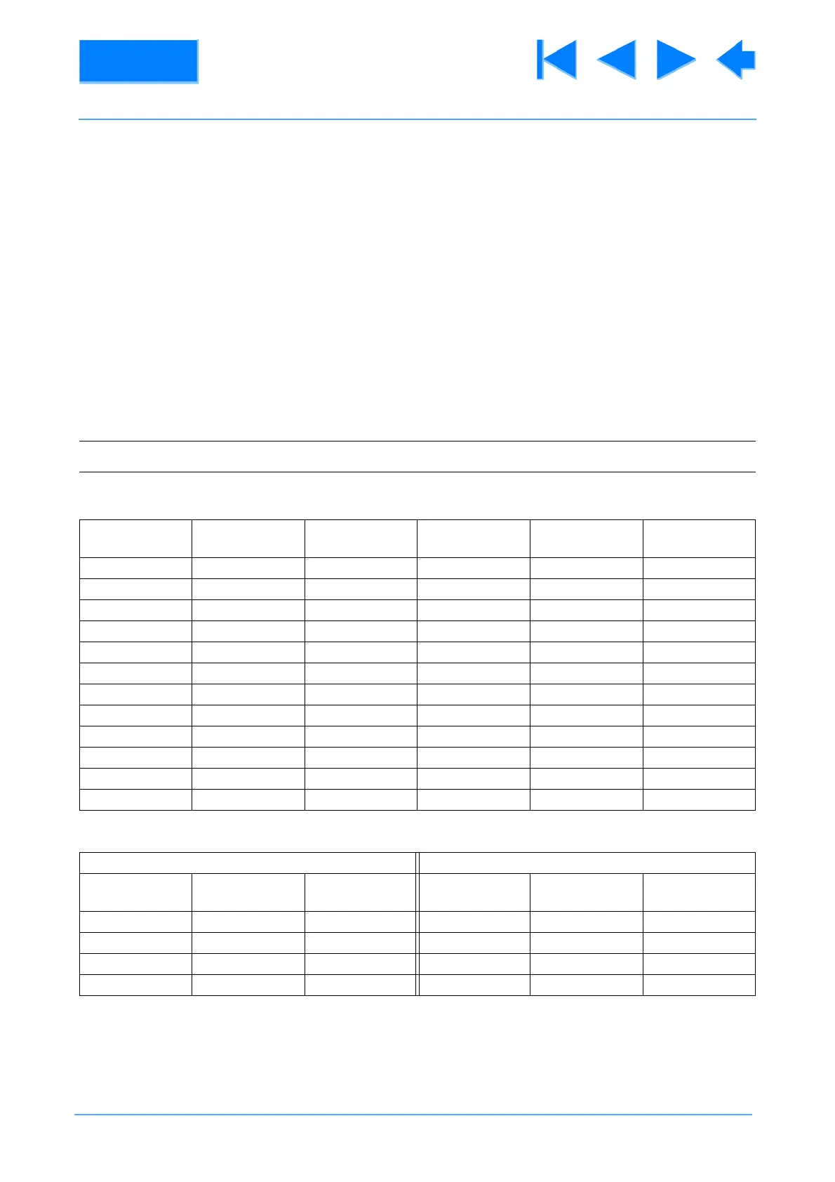
Table 2.1 250 E Encoder Pin Designations
Encoder
Connector
Encoder Wire
Colour
Connector Pin
No.
Encoder
Connector
Encoder Wire
Colour
Connector Pin
No.
Pan A1 Black 1 Tilt A1 Black 13
Pan A2 Brown 2 Tilt A2 Brown 14
Pan A3 Red 3 Tilt A3 Red 15
Pan A4 Orange 4 Tilt A4 Orange 16
Pan A5 Yellow 5 Tilt A5 Yellow 17
Pan A6 Green 6 Tilt A6 Green 18
Pan B1 Blue 7 Tilt B1 Blue 19
Pan B2 Violet 8 Tilt B2 Violet 29
Pan B3 Grey 9 Tilt B3 Grey 21
Pan B4 White 10 Tilt B4 White 22
Pan B5 Pink 11 Tilt B5 Pink 23
Pan B6 Cyan 12 Tilt B6 Cyan 24
Table 2.2 250 IT RS Interface Connectors
RS-232 RS-422
Function Wire Colour Connector Pin
No.
Function Wire Colour Connector Pin
No.
TX Red 2 TX- Brown 2
RX Orange 3 RX- Black 3
Gnd Black 5 TX+ Violet 7
RX+ Green 8