7
Introduction
The Vision 6 pan and tilt head embodies an adjustable spring counterbalancing mechanism, LF
drag assemblies for pan and tilt motions and an adjustable camera mounting plate.
The balance system is easily adjusted by a knob (2) on the rear of the head. Maximum and mini-
mum payloads that can be balanced, and tilt ranges, are dependent on the weight of the camera
and accessories and on the centre of gravity (C of G) height.
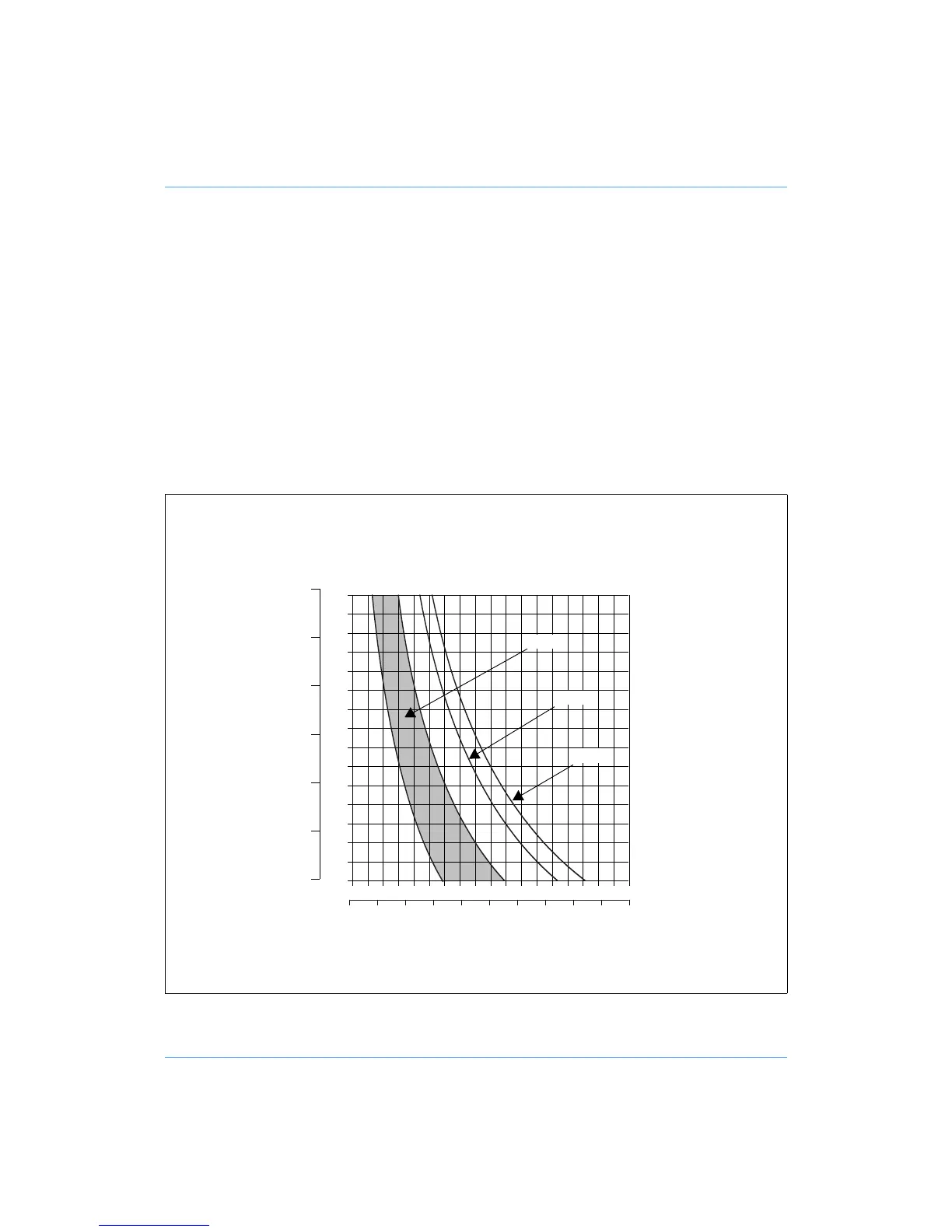
The graph shows the range of load and C of G height that can be maintained in balance. The shad-
ed area of graph corresponds to those load/C of G combinations that can be balanced over the
full tilt range. The areas to the right indicate the progressively reducing tilt range with greater load
and higher C of G.
Where a load/C of G combination falls outside of the graph it will be necessary to increase or de-
crease the weight or the C of G height - if possible - to enable the head to balance the load.
Balance graph
14 16 18
kg
20
32 36 40 lb444
4 10 12
8 12 16 20 24 28
2 6 8
90
100
130
2
3
4
5
6
7
8
110
120
140
150
160
170
180
190
200
80
70
60
in. mm
50
±90°
±60°
±40°