INSTALLATION
+++++++,
+++1
,5# iJ
(7)
g
.................. @
--.
_ OURCE
MENU
_ CH+
©
CH-
¢.
_ VOL+
_ VOL-
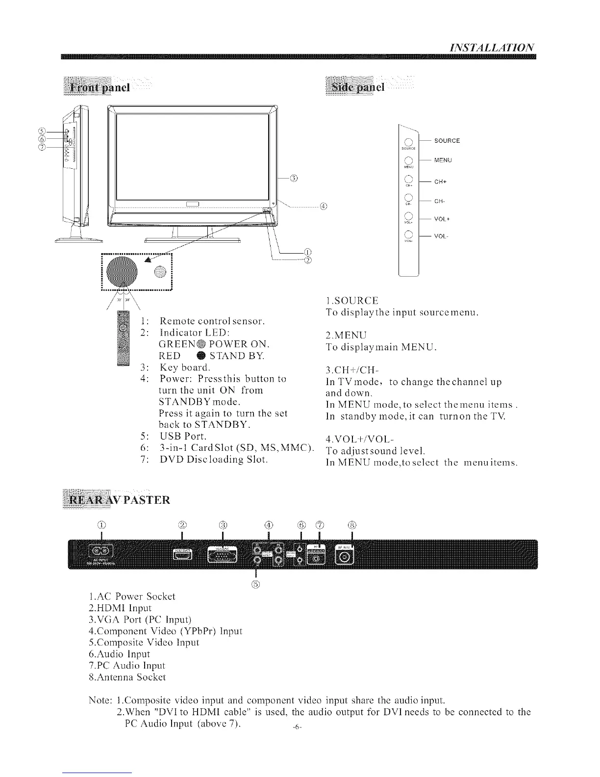
I: Remote control sensor.
2: Indicator LED:
GREEN@ POWER ON.
RED • STAND BY.
3: Key board.
4: Power: Pressthis button to
turn the unit ON from
STANDBY mode.
Press it again to turn the set
back to STANDBY.
5: USB Port.
6: 3-in-I CardSlot (SD, MS,MMC).
7: DVD Discloading Slot.
1.SOURCE
To displaythe input sourcemenu.
2.MENU
To displaylnain MENU.
3.CH_/CH-
lnTVmode, to change thechannel up
and down.
In MENU mode,to select thelnenu items.
In standby mode, it can turnon the TM
4.VOL +/VOL-
To adjustsound level.
In MENU mode,to select the menu items.
© ® ® ® ® © ®
®
I.AC Power Socket
2.HDM1 Input
3.VGA Port (PC Input)
4.Colnponent Video (YPbPr) Input
5.Colnposite Video Input
6.Audio Input
7.PC Audio lnput
8.Antenna Socket
Note: 1.Colnposite video input and component video input share the audio input.
2.When "DV1 to HDM1 cable" is used, the audio output for DV1 needs to be connected to the
PC Audio Input (above 7). __,_