EasyManua.ls Logo

Viper 550 ESP User Manual

Viper 550 ESP
52 pages
To Next Page IconTo Next Page
Page #1 background imageLoading...
Page #1 background image
550 ESP
Installation Guide
© 2001 Directed Electronics, Inc. Vista, CA N553 8-01
Rev. M 1.1
®
®
NEW!
Outboard XHF Receiver for
Extended Range

Table of Contents

Question and Answer IconNeed help?

Do you have a question about the Viper 550 ESP and is the answer not in the manual?

Viper 550 ESP Specifications

General IconGeneral
BrandViper
Model550 ESP
CategoryCar Alarm
LanguageEnglish

Summary

What is Included

Warning! Safety First

Installation Points to Remember

Before Beginning the Installation

Important pre-installation steps and warnings.

Finding the Tachometer Wire

Steps to locate and test the vehicle's tachometer wire.

Finding the Wait-to-Start Bulb Wire for Diesels

After the Installation

Steps to follow after completing the installation.

Primary Harness (H1), 12-Pin Connector

Secondary Harness (H2), 3-Pin Connector

Remote Start Primary Harness, 5-Pin Connector

Heavy Gauge Relay Satellite Key Switch Interface

Remote Start Secondary Harness (H3), 6-Pin Connector

Primary Harness (H1) Wire Connection Guide

H1/1 ORANGE (-) Ground-When-Armed Output

Explains the function and connection of the H1/1 ORANGE wire.

H1/2 WHITE (+/-) Selectable Light Flash Output

Details the H1/2 WHITE wire's light flash output configuration.

H1/3 WHITE/BLUE Remote Start (-) Activation Input

H1/4 BLACK/WHITE (-) 200 mA Domelight Supervision Output

H1/5 GREEN (-) Door Trigger Input, Zone 3

H1/6 BLUE (-) Multiplex Input, Zone 4

H1/7 VIOLET (+) Door Trigger Input, Zone 3

H1/8 BLACK (-) Chassis Ground Connection

H1/10 BROWN (+) Siren Output

H1/11 RED (+)12V Constant Power Input

H1/12 RED/WHITE Channel 2, 200mA (-) Output

Secondary Harness (H2) Wire Connection Guide

H2/1 GRAY/BLACK (-) Diesel Wait-to-Start Bulb Input

Guide for connecting the H2/1 GRAY/BLACK wire for diesels.

H2/2 LIGHT GREEN/BLACK (-) Factory Disarm Output

H2/3 VIOLET/BLACK 200 mA (-) Channel 4 Output

Relay Satellite Key Switch Interface Wire Connection Guide

RED (2) (+)12V Input for Relay

Instructions for connecting the RED wires for relay power input.

PINK (+) Ignition Output

Details the PINK wire for ignition output.

ORANGE (+) Accessory Output

Explains the ORANGE wire for accessory output.

PURPLE (+) Starter Output

Describes the PURPLE wire for starter output.

PINK/WHITE (+) Second Ignition Output

Details the PINK/WHITE wire for second ignition output.

Remote Start Secondary Harness (H3) Wire Connection Guide

H3/1 BLUE (-) Status Output

Explains the H3/1 BLUE wire for status output.

H3/2 BLUE/BLACK (-) Optional Third Ignition Output

Details the H3/2 BLUE/BLACK wire for third ignition output.

H3/3 GRAY (-) Hood Pinswitch Input, Zone 1

H3/4 BROWN (+) Brake Switch Input, Zone 1

H3/5 VIOLET/WHITE Tachometer Input

H3/6 BLACK/WHITE Neutral Safety Switch Input

Neutral Safety Switch Interface

Testing the Neutral Safety Switch

Procedure for testing the neutral safety switch functionality.

Bypassing GM Vehicle Anti-Theft Systems (VATS)

1995 and Newer Vehicle Anti-Theft Systems (Immobilizers)

Passlock I and Passlock II (PL-1 and PL-2)

Information on Passlock I and II systems in GM vehicles.

Passkey III (PK-3), Transponder-Based Systems

Details on Passkey III and other transponder systems.

Plug-In LED and Valet/Program Switch

Programmer Interface, 3-Pin Black Plug

Shock Sensor Harness, 4-Pin Connector

GREEN (-) Multiplex Input, Zone 2

Explains GREEN wire for multiplex input and zone 2.

BLUE (-) Multiplex Input, Zone 2

Explains BLUE wire for multiplex input and zone 2.

RED and BLACK: RED is (+)12V Constant, BLACK is (-) Ground

Describes RED and BLACK wires for shock sensor.

Tach Learning

Door Lock Harness (H4) Wire Connection Guide

Type A: (+) 12V Pulses from the Switch to the Factory Relays

Type B: (-) Pulses from the Switch to the Factory Relays

Type C: Reversing Polarity

Type C: Reversing Polarity, cont.

Type D: After-Market Actuators

Type E: Mercedes-Benz and Audi (1985 & Newer)

Type F: One-Wire System

Type G: Positive (+) Multiplex

Single-Resistor Type

Describes single-resistor type in positive multiplex systems.

Two-Resistor Type

Describes two-resistor type in positive multiplex systems.

Determining the Proper Resistor Values

Steps to determine resistor values for Type G systems.

Type H: Negative (-) Multiplex

Single-Resistor Type

Describes single-resistor type in negative multiplex systems.

Two-Resistor Type

Describes two-resistor type in negative multiplex systems.

Determining the Proper Resistor Values

Steps to determine resistor values for Type H systems.

Internal Programming Jumpers

Tach Threshold On/Off

Controls the tach circuit's trigger threshold for different vehicles.

Light Flash (+/-)

Sets the polarity for the light flash output.

Transmitter/Receiver Learn Routine

Transmitter Configurations

Standard Configuration

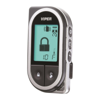
Describes standard remote configuration for arming/disarming.

Single Button Arm/Disarm Configuration

Details single button configuration for arming/disarming.

Multi-Level Security Arming

System Features Learn Routine

Feature Menus

Menu #1 - Basic Features

Lists basic system features and their settings.

Menu #2 - Advanced Features

Lists advanced system features and their settings.

Menu #3 - Remote Start Options

Feature Descriptions

Menu #1 - Basic Features

Detailed descriptions of basic system features.

Nuisance Prevention Circuitry™

Valet Mode

Timer Mode

Table of Zones

Shutdown Diagnostics

To Perform Shutdown Diagnostics

Steps to diagnose system shutdowns using LED flashes.

Long Term Event History

Safety Check

Troubleshooting

Alarm Troubleshooting

Common issues and solutions for alarm functions.

Remote Start Troubleshooting

Wiring Quick Reference Guide

Related product manuals