Quick Reference
Install
Guide
Security and Remote Start
Responder
LC3
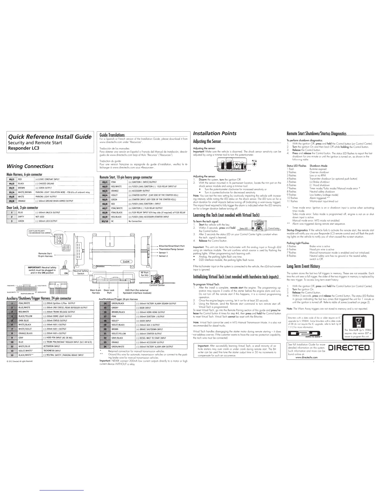
Wiring
Connections
Main
Harness,
6-pin
connector
MJ/1 .
REO
'\
lft/2
BLAC
K
,d l_
l/)
BR
OWN
(+
)1
2V
DC
CO
NS
TAN
T
IN
PU
:_T
___
______
-j
(-)
CHA
SSIS
GR
OUN
D
(+
)SIREN
OU
TPU
T
~r
~
4
-t;f.
W
HIT
E/
BRO
WN
PARKING
UGH
T
ISOLATI
ON
WI
RE
- P
IN
87a
of
onboard relay
~
~
~
·
·
~
~~
~
··i
+-
W_HI_
TE
__
~
~
P
_
AR
_
K
_
IN
_
G
_
U
_
GH
_
T
_
O
_
UT
_
P
_
U
T
____
_
__
..
.
________
Ji
J.tl~
;ffl;
ORAN
GE
(
-)
50
0mA
GR
O
UN
D
WH
EN
AR
M
ED
OUTPUT
C2012Direct
ed.AI
I
rightsRe5
eNed
.
(-)
50
0mA
U
NLOC
K O
UT
PUT
NOT
USED
H 50
0mA
LOCK OU
TP
UT
Remote Sta rt
10-p
in
Harness
Guide
Translations
For
a Spanish or French ver
si
on of t
he
Insta
ll
a
ti
on
Gu
ide, please
down
l
oad
it
from
www.directechs.com
un
der
NResources"
Tr
aducci6n
de
los manuol
es
P
ara
obtener una ver
siOn
en
Espafiol o F
rances
del
Manua
l
de
lnstol
oc
i
On,
desc6r·
gue
la
de
WVV\o'.J.directec
hs.
com
bajo
el tit
ulo
"Recursos" ("Resources"
).
Traduction d u guide:
Po
ur
une
version franyaise ou e
spa
gn
ole
du
guide d'instollation, veuillez
le
r
e-
l
&harge
r 0
\111\fv'W
.di
rec
te
chs.com
sous
«Reso
urces• ..
Bit
writer
/S
martStart
Port
Re
qu
ir
ed connec
ti
on for manual transmission vehicle
s.
Ground
th
is
wir
e for automatic t
ra
nsmi
ss
ion vehicles or connect
to
the
park-
ing broke
wire
for manual t
ra
ns
mission vehicles
Important:
NEVER
connect
200
mA l
ow
current outputs
diredy
to
a motor or high
current
devic
e
WITHOUT
a r
elay
Installation Points
Adjusting
the
Sensor
Adjusting
the
sensor:
Important!
Make
sure
the
vehicle is disarmed. The shock sensor sensi
ti
vi
ty
can be
ad
j
us
ted
by
usi
ng
a trimmer tool to
turn
the potentiometer
Adjusting
the
sensor:
1 Disarm
the
system,
turn
the
i
gn
it
ion
Off
2.
With
the
sens
or mo
un
ted in
its
permanent location, loc
ale
t
he
tr
im pot on
the
shock sensor module and
us
ing a trimmer tool
Turn
the
potentiometer
clockw
i
se
f
or
inc
re
ased
sens
itivity or
Turn
it counterclockwi
se
for
dec
reased
se
nsitivi
ty
Note
:
You
can
rest
the new setting by cautiously
im
pac
ting t
he
veh
icle with increas-
ing intensity while noting
the
LED
status
on the shock
sensor.
The
L
ED
tu
rn
s on for a
short duration for small impac
ts
before turning off
[i
ndicating a warn-away trigge
r)
Th
e impo
ct
level required to fully
tri
gger
the alarm
is
indicated
whe
n
the
LED
remai
ns
on for a longer d
ur
ation before t
urn
ing off.
To
learn the tach signal:
1 Start
th
e vehicle with the k
ey.
2.
Withi
n 5 seco
nds,
press and hold
Sto
tu
5
LED
-
Contro
l
OOtton
the Cont
rol
button
After 3 seconds the status l
ED
on your Control Center
li
ghts constant when
the tach signal
is
learned
4.
Release
the
Control button.
Important
This
un
it con lear n
the
tachometer w
it
h
th
e analog input or
th
rough
d2d
us
ing an interface modul
e.
The
un
it conf
irm
s which
sou
rce
is
used
by
fl
ashing t
he
park
in
g lights.
When
programming tach learning w it
h:
Analog, t
he
parking lights
fl
ash one time.
D2D
interface modul
e,
the parki
ng
li
ghts flash twice
If
the tachometer input on
the
system
is
connected
to
the vehicle, the
d2d
tachometer
input
is
ignored
lnitiollzing_llirtual
Tach
(not
needed
with
hardwire...tach_inp.utsL
To
program
Virtual
Tach
:
1.
After
the
in
sta
ll
is
comp
lete, remote start the engine. T
he
programming op-
eration may require 3 cranks of the starter before t
he
engine
starts
and r
uns.
Do not
tu
rn
off t
he
remote start if
th
is
hap
pens,
it
is
a normal programming
operation.
2.
Once
the engine begins running, let
it
run
for at least
30
seconds.
3 Using
the
Remo
te, send the Remote
star
t command to t
urn
remo
te
start o
ff
.
Virtual
Tac
h
is
pr
og
rammed
To
reset Vir
tu
al
Tach
,
go
into t
he
Rem
o
te
Pairing section
of
th
is
guide and pres
s/
re-
lease the
Con
trol
bu
tton 4 t
im
es
for step
#4,
then
pr
e
ss
and hold the Control button
to reset Virtual
Ta
c
h.
Virtual
Tach
cannot be
reset
w
it
h
the
Bitwr
iter.
Note:
Vi
r
tu
al
Tach cannot be
used
in
MTS
Manual
Transmission M ode.
It
is
al
so
not
recommended for diesel t
ru
cks
Vi
rtual
Ta
ch handl
es
di
se
ngaging the starter motor during remote st
ar
ti
ng -
it
doe
s
·not
addr
ess
over-
rev.
If
the
customer wants to have
the
ove
r-
rev protection ca
pab
il
ity,
the tach wire
must
be
co
nnected
Important: After successfully learning
Vir
t
ua
l
Tac
h, a
sm
al
l
mi
nori
ty
of ve
hi
de
starters may over cran k
or
under crank d
ur
ing remote
star
t. The
Bit-
wr
i
ter
ca
n
be
used fine tune t
he
starter output
ti
me
in
50
ms
incremen ts to
compensate for
suc
h on occurrence.
Remate..start.Shutdo.wn/Startup
Diagnostics
To perform shutdo
wn
diagno
stics:
1.
With
the ignition Off,
pre
ss
and hold
the
Co
nt
rol
button [on Control Center).
2 Turn
the
ignition
On
and then back
Off
while holding
the
Control bu
tt
on
3.
Release
th
e
Co
nt
rol
button.
4.
Pres
s a
nd
release
the
Control button .
The
s
tat
us
L
ED
flashes to report the last
shutdown f
or
one minute o r
un
ti
l t
he
ignition
is
turned on, as shown in t
he
following table:
Status
LED
Flashe
s
l
llas
h
2
1las
hes
J
llas
hes
Shutdown
Mode
Runtime
expired
Over
-
rev
shu
t
down
Low or no
RPM
4llash
es
5
1las
hes
Transm
i
tter
shutdown (or
op
tional
push
button)
[+I
Broke shutdown
6
1la
shes
H
Hood
shuldown
71lashes
8 flashes
Tim
er
mode/Turbo
mode/Manual
mode error *
Neu
tral safety shutdown
9f
lashes
Low battery [voltage mode)
10
llash
es
Alarm
tri
ggered * *
I I l
la
shes
Wolt
·l
o-sta
rt input timed out
Timer mode
er
ror: Ignition is on or shutdown input is active when activating
timer mode.
Turbo
mode error:
Tu
rbo
mode
is
programmed off, e
ng
ine
is
no
t on or
shu
t-
down
in
put is active.
r'v\on
uol m
ode
error: MTS mode not enabled
Alarm was
tr
i
gg
ered during remote start seque
nc
e.
Startup Diagnostics:
If
t
he
vehicle fails to activate t
he
remote
sta
r
t,
the remote start
module
wi
ll
no
li
~
you via your Responder LC3 remote control and
wi
ll flash
th
e park-
i
ng
lights on
th
e vehicle to notify you of
wha
t caused
the
no-start situation
Parking
light
Flashes
5 flas
hes
Broke
wire
is active
6 flashes
Hood
pin
wi
re
is
active
7 flashes
Ma
nual tran smission m
ode
is
enabled and not initialized
8 flashes Neutral safety
wire
has no ground or the
neutr
al safety
switch
is
Off
longJeun
Event
History
The
system
stores the last
two
full
tr
iggers
in
memory.
These
are not erasable. Each
time the
un
it
sees
a
fu
ll trigger,
the
olde
r of t
he
two triggers in
mem
ory
is
repl
aced
by
the
new
trigger.
To
access long
term
event
hist
ory:
W
it
h
the
ignition
Off
, press a
nd
hold the
Con
t
rol
button
(on
Co
ntrol Center)
Turn t
he
ignition
On
Release the
Co
ntrol button.
4.
W
it
hin 5 seconds, press and release t
he
Control button . T
he
stat
us
l
ED
flashes
in groups indica
ti
ng the lost two zones that triggered
the
unit f
or
l minute or
un
til t
he
ignition is turned off.
Refer
to t
ab
le of zones [ove
rl
eaf
on
page
21
Note:
The
Warn
Aw
ay
triggers are not stored to memory and
is
not r
epo
rted.
Bitwr
iters
with a
date
code
of
6a
or
ol
der
r
equi
re
an
IC
upg
rade
(p/
n 998M).
Some
bi
iiN
rit
ers
with
o
date
code
of
6B
do
no
t
requir
e t
he
IC
upgra
de
, ref
er
to
tec
h tip #
11
12
lor
mo
re
infor
ma
ti
on.
'·
______
_.....
.•
OATA
TO
OATA
.
..
The
Bi
iiN
riter®
(p/n 998UI
r
equires
chip
version
2.7
or
newer
to pr
ogram
th
is
uni
t.
See
fu
ll
I
ns
tallation G
ui
de
for more
detailed information on this system.
D I R E
CTE
De
Such
in
formation and more can
be
found online
at
www
.directechs.c
om