Document: CL140072 L2174 Manual Issue 2.0 Page 24 of 26
10.3 Down Converter Type
The following sequence defines the changes and sequence required when selecting the required down converter
and receiver RF frequency:-
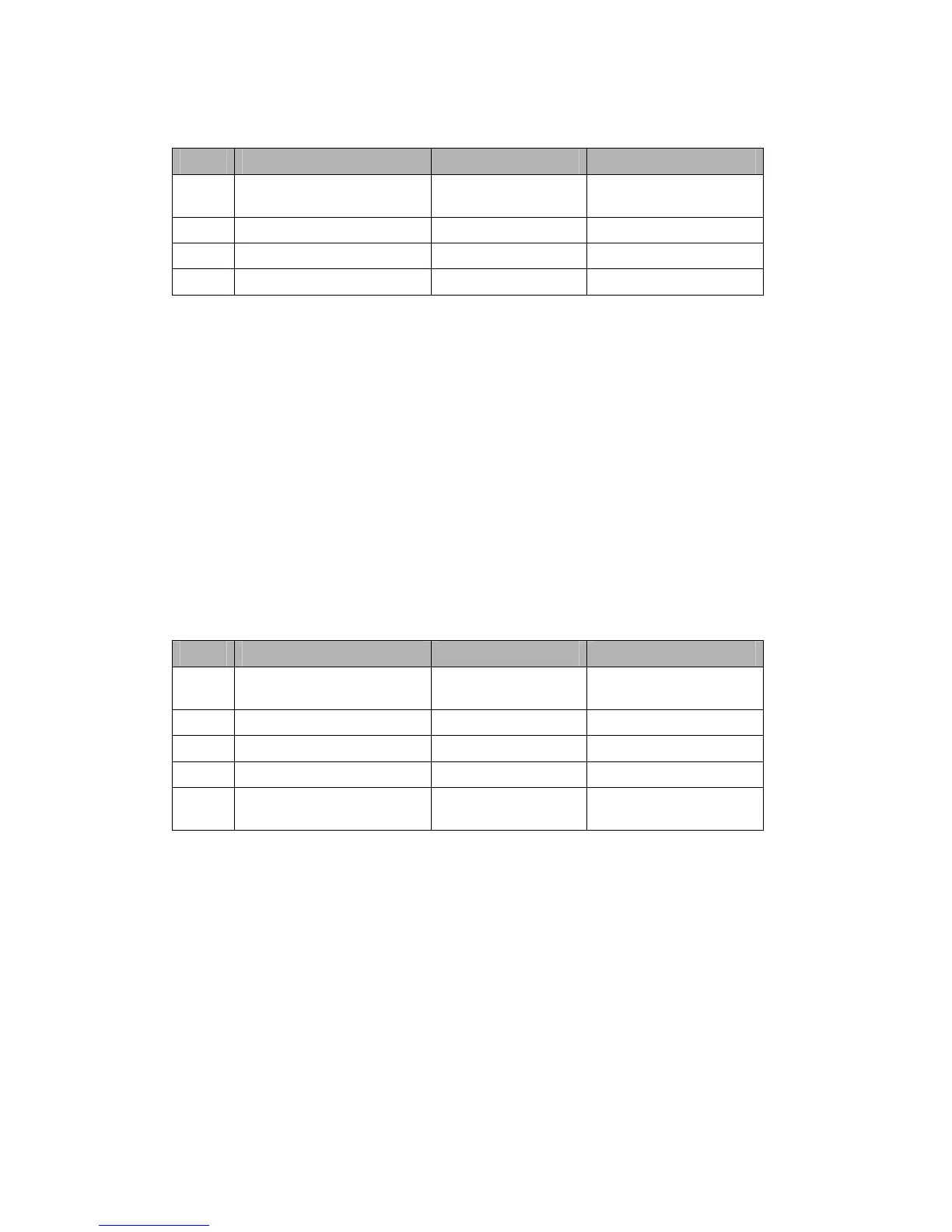
Step Menu Option
Setting
1 Demodulator Æ
DownconvertersÆ Channel 1
Set All Inputs Yes
2 Downconverter Select Type
3 Power On
4 Home Display * Frequenc
The demodulator will automatically detect code rate, if configured as in section 10.2
The received demodulation settings will then be displayed on the Home Display.
10.4 Decoder
The Decoder can be operated in different modes, which need to be set by the operator (it will not automatically
switch modes). These are:
• Low Delay MPEG2 Standard Definition
• Low Delay MPEG2 High Definition
• Generic MPEG2 High Definition
• Generic MPEG2 Standard Definition (not supported yet)
• H.264 High Definition
• H.264 Standard Definition (not supported yet)
It can be switched to decode a transport stream either from the demodulator output, the Packet Diversity
output, an external source from the rear panel ASI In socket, or the IP to Transport Stream block (if licensed).
In Auto Service mode, the first available service in the transport stream will be decoded.
Step Menu Option
1 Decoder Æ Decoder Config Æ
Decoder Options
uto Service On
3 Stream Management ÆRouting Diversit
4 ″ Mode Basic
5 ″ Source Demodulator*/ Diversity*/
External ASI/ IP
* Only one of ‘Demodulator’ or ‘Diversity’ will be displayed, depending on whether Diversity is On or Off
10.5 Deinterleaving
Please see 4.1 for a functional block diagram of the L2174 receiver.
The interleaver settings on the encoder define the required FEC (1/2 – 14/15) and also the required Burst
duration.
If the deinterleaver is ‘On’ no other parameters need to be set, as the deinterleaver will automatically extract the
FEC and ‘burst’ settings from the received stream.
The resultant ‘Interleave Delay’ and ‘Interleave Burst’ are then also displayed on the L2174.
These parameters are a function of the Interleave FEC, Interleave Burst correction settings in the encoder and
also the ASI bitrate.
The ‘Delay’ is a function of the Interleave FEC value and Burst duration set on the transmitter interleaver.
Delay = Burst * Denom; where Denom is the FEC denominator.
For example :- Burst setting of 1000ms and FEC of 3/4 will result in a delay of 4000ms.
 Loading...