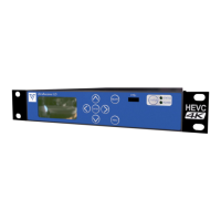
Document: CL140072 L2174 Manual Issue 2.0 Page 6 of 26
4 INTRODUCTION
The Lynx Receiver range are highly flexible, high performance products based on compact DVB-T and LMS-T
demodulators using VISLINK’s Maximum Ratio Combining diversity algorithm, and a combined HD/SD
decoder.
The ultra low delay MPEG2 SD/HD Decoder has been speed optimised to operate with the Link Research Ltd
family of MPEG2 Encoders, which utilise field encoding. This range of decoders will not support frame
decoding. A licensable upgrade will allow support for B-Frame or ‘Generic’ MPEG2 Decoding that will support
frame decoding, but at higher delay.
The Decoder can also be licensed to support H.264 decoding. This will be available in different levels from
Main Profile 4:2:0 8 bit, up to High Profile 4:2:2 10 bit.
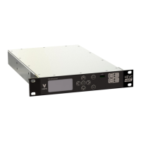
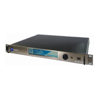
The product range is based on three hardware variants: Demodulator-only (L2074), Decoder-only (L2170) and
Demodulator-Decoder (L2174). All other variants are licensable and therefore allow for field upgrades by
changing the license to enable extra features as required. Please contact VISLINK for details.
This document has been written primarily for the complete L2174 Receiver. Where there are major differences for the L2170 and
L2074 variants they will be indicated, however some minor differences may not always be documented.
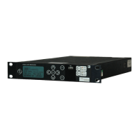
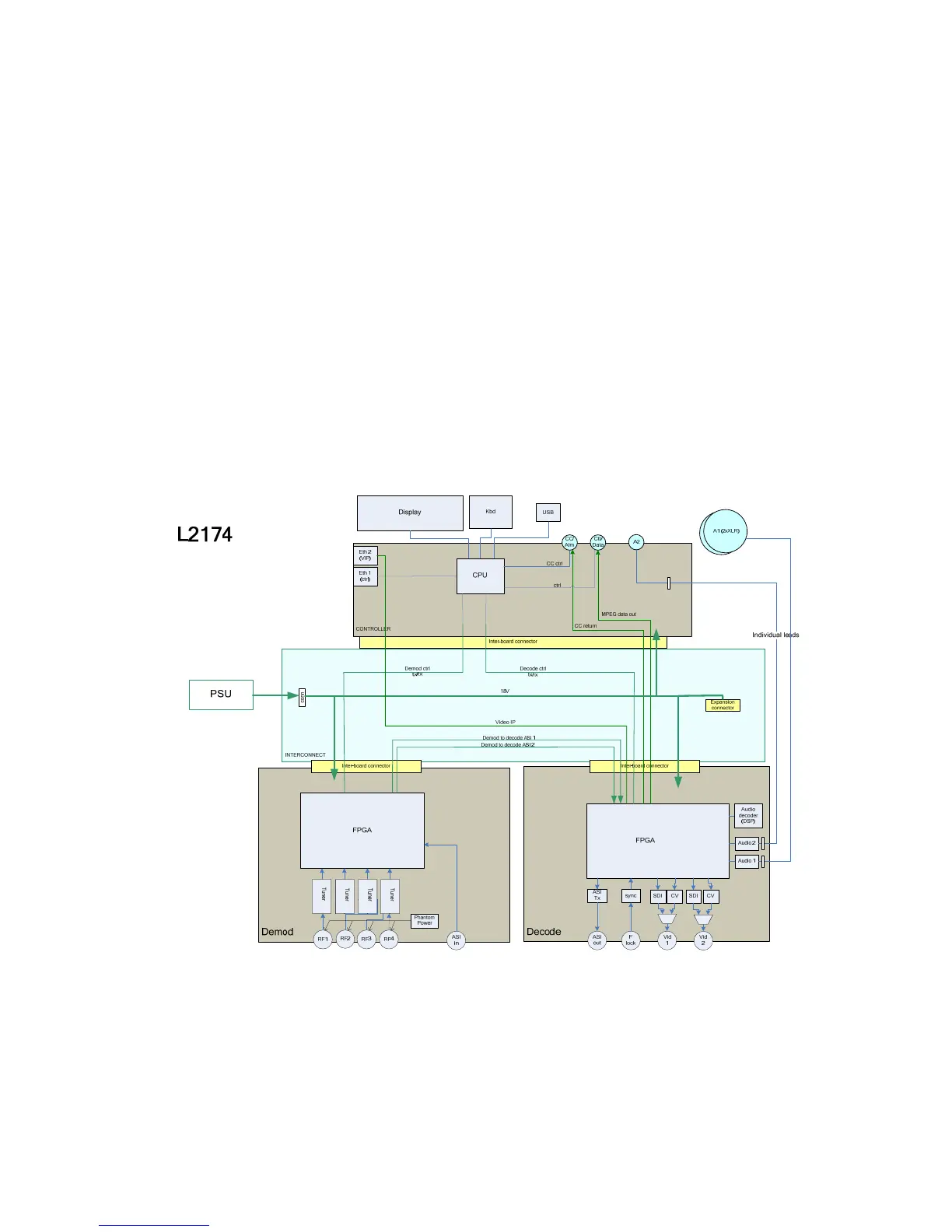
4.1 L2174 Internal Architecture
The L2174 is based on 3 main hardware components: Demodulator card, Decoder board and Controller board.
The L2074 & L2170 products do not have the Decoder and Demodulator boards fitted (respectively). Please
note that upgrading one of these to a full L2174 requires the unit to be returned to VISLINK.
As shown in the block diagram above, the Demodulator board generates an ASI stream from the RF inputs
and/or the external ASI, then passes this to the Decoder board to generate the Video and Audio outputs. In
addition, the Decoder extracts embedded (or ’wayside’) RS232 data if it is present in the transmission, as well as
return data from a VISLINK Camera Control System. There are 2 ASI connections between the boards to
allow extra flexibility in how the unit is configured (see later).
 Loading...