Do you have a question about the Vislink UltraReceiver and is the answer not in the manual?
Information for personnel on potential hazards, RF power, and specific component warnings.
Guidelines for safe disposal of batteries and equipment, adhering to environmental directives.
Caution to protect the unit from water/fluids and use a rain cover outdoors.
Details on calculating safe working distances from RF radiation and general safety precautions for operators.
Vislink's adopted power density limits based on IEEE and ICNIRP standards for controlled environments.
Instructions to ignore RF and Demodulator functions for decoder-only models.
Information on checking the Vislink website for the latest firmware revision.
Overview of the UltraReceiver's three main hardware components: Demodulator, Decoder, and Controller boards.
Specifies DVB-T and LMS-T modulation types, QAM levels, and bandwidth options.
Lists supported decoder codecs including HEVC, AVC, MPEG-2, and AAC.
Details supported video formats like 720p, 1080i, 1080p, and 2160p resolutions.
Outlines UHD, HD, and SD video profiles with associated bitrates and color formats.
Lists all available input types: UHF, ASI, Frame Lock, Camera Control, and Ethernet.
Details the available outputs: embedded audio, ASI, and analog audio.
Specifies the types and standards of video outputs: 4x 3G-SDI and 4x HD-SDI.
Lists supported video formats, including future options, with resolution and frame rates.
Specifies supported audio formats like MPEG-1 Layer 1/2 and SMPTE 302M.
Describes the physical dimensions, weight, and power requirements of the unit.
Lists operating temperature range (0°C to 50°C) and humidity limits (95% non-condensing).
Mentions the Diversity Receiver 2-RF to 4-RF input upgrade option.
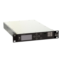
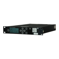
Provides a visual overview of the unit's front panel input/output connectors.
Summarizes all input and output connections, referencing section 3.13 for details.
Details the pinout configurations for various connectors like RF, ASI, Frame Lock, and Video Outputs.
Describes the 75Ω BNC connectors for RF inputs, including UHF frequency range and sensitivity.
Specifies the 75Ω BNC connector for ASI input and its compliance standard.
Details the 75Ω BNC connector for frame lock input (Black/Burst or Tri-level sync).
Describes the 75Ω mini BNC connectors for 4x 3G HDSDI and HDSDI outputs.
Specifies the 75Ω BNC connector for ASI output and its function.
Details the LEMO connector for CTRL/Data, including its pinout and function for camera control.
Describes the 3-way XLR connectors for Audio 1 output, including pinout and analogue mode specifications.
Describes the LEMO connector for Audio 2 output, including pinout and analogue mode specifications.
Details the LEMO connector for Camera Control/Alarm, including pinout and status output functionality.
Explains the Ethernet port for control via Web Browser (HTTP) and SNMP.
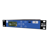
Visual representation of the UltraReceiver's front panel controls and indicators.
Explains the function of MENU and ESCAPE keys for navigation and operation.
Describes the use of arrow keys, ENTER, and ESCAPE for menu navigation and parameter adjustment.
Details the STATUS key's function to access ALARMS and view signal strength/MER.
Illustrates the display of MER for the four RF channels.
Explains the meaning of the STATUS, POWER, and LOCAL/REMOTE LEDs.
Describes the function of the USB port for code updates.
Explains how to access and configure demodulator settings like Input Mode, Demodulator Setup, and Downconverters.
Allows selection of LMS-T or DVB-T modulation schemes and enabling/disabling individual inputs.
Details configuration of Frequency, Bandwidth, Guard Interval, and Polarity with auto modes.
Guides on selecting downconverter types and powering them for RF inputs.
Covers configuration of decoder inputs, services, audio, and video formats for decoding.
Configuration of the input source for decoding.
Entry of PID's for each parameter to ensure correct service decoding.
Configuration of the audio format of the service for correct decoding.
Configuration of the video format of the service for correct decoding.
Controls video synchronization modes (OFF, ON external/internal) and offset adjustments.
Provides options for saving/recalling presets, configuring control interfaces, and managing defaults.
Functionality to save up to 16 preset configurations and dump them to a USB stick.
Configuration of external control interfaces like Web Identifier, Ethernet Port, and Status Pin.
Options to restore factory defaults or reboot the unit.
Section for entering license codes and viewing licensed features.
Setting the unit's time and date and viewing accumulated run-time.
Displays useful information for contacting Vislink, including module versions.
Displays detailed performance information like errors, locks, temperatures, and test results.
Note regarding availability of this option.
Shows the menu structure for HCAM, noting context-sensitive and license-dependent options.
Procedure for connecting the UltraReceiver to a PC via RJ45 for webserver configuration.
Steps to access the unit's web interface using its IP address in a browser.
Webpage providing a diagrammatic view of the signal routing within the receiver.
Details the three main operating types for the demodulator: Single Pedestal LMS-T, Dual Pedestal LMS-T, and DVB-T.
Describes the steps and sequence for changing to DVB-T operation mode.
Outlines the steps and sequence for changing to LMS-T operation mode.
Explains how selecting downconverter type defines frequency ranges and spectral inversion.
Describes switching the decoder to process transport streams from demodulator output or ASI input.
Explains deinterleaving settings and how they extract FEC and burst settings from the stream.
Describes encapsulating ASI streams into IP for transport over Ethernet, with limitations.
Steps for sending video over IP between units using a direct Ethernet connection.
Details various decryption options and license requirements for encrypted streams.
Option to use third-party down converters, allowing individual configuration and storage.
Information on purchasing additional features via licenses from a local representative.
Instructions for upgrading the UltraReceiver firmware using the Vislink website.
| Input Connections | BNC |
|---|---|
| Output Connections | BNC, HDMI, XLR |
| Demodulation | QAM |
| Audio Output | Analogue (XLR), Digital (XLR) |
| Channel Bandwidth | 6, 7, 8 MHz |
| Modulation | QAM |
| Dimensions | 19" |