Do you have a question about the Vislink Quantum and is the answer not in the manual?
Information contained in this manual is property of Vislink and may not be reproduced without permission.
Add any additional Trademark content from external companies.
Explanation of how NOTE, CAUTION, and WARNING are used to convey information.
Provides worldwide support contacts and instructions for contacting technical support.
Ensures awareness of potential hazards for personnel operating or maintaining the equipment.
Instructions for proper disposal of the equipment and batteries, following environmental directives.
Information on protecting the unit from water and fluids, especially when used outdoors.
Details on safe working distances from transmitting antennas and potential RF radiation effects.
Guidelines for RF power density limits based on IEEE and ICNIRP standards.
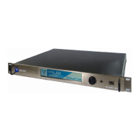
Description of the Quantum Receiver's design for receiving wireless camera transmitter output via RF and IP.
Information on the firmware version covered by this manual and how to verify it.
Block diagram illustrating the receiver's functions and connector relationships.
Highlights of the Quantum Receiver's capabilities, including diversity, decoding, and IP connectivity.
Details on various licenses available to add functionality to the base configuration.
Details on the unit's dimensions, weight, temperature, humidity, and power requirements.
Specifications for RF inputs, frequency band, demodulation, and receiver threshold.
Specifications for IP input and output capabilities, including protocols and bandwidth.
Parameters for video decoding standards, formats, outputs, and audio specifications.
Details of the four RF input coaxial connectors for receiving UHF input 70MHz to 860MHz.
Description of Asynchronous Serial Interface (ASI) and Genlock connectors for signal transport.
Information on SFP transceiver modules for transmitting Serial Data Interface (SDI) signals.
Details of the two 5-pin Lemo connectors for audio output pairs and channels.
Description of two SFP expansion sockets for future expansion of the unit.
Connector for connection to the FocalPoint wireless camera control for serial data return.
Connectors for OCP, user data (RS232/RS485/TTL) or Tally (Red/Green Wet/Dry).
Details of WAN and LAN ports for web browser control, network management, and video transmission.
USB ports on the rear and front panel for inserting a USB memory stick for code updates.
Description of the standard IEC 3-way connector for the 100-240V AC power supply.
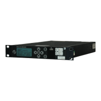
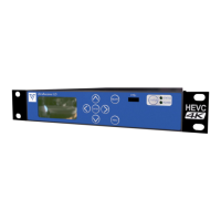
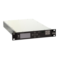
Overview of the front panel touch-screen display and rotary control for navigation and selection.
Description of the rotary control's function for scrolling, selecting, and modifying values.
Indicates the headphones socket is for future use and should not be used currently.
Indicates the USB port is for future use and should not be used.
Details on how the touch-screen displays status messages and provides navigation buttons.
Description of the Home screen displaying RF input status and quality with associated parameters.
Details on the Setup screen for configuring Demod, Rx, Decoder, Streams, Network, and Analog settings.
Description of the Info screen displaying receiver settings that cannot be edited.
Description of the Status screen displaying detailed settings for Demod, Rx, Decoder, Streams, Network, and Analog.
Introduction to the web-based Graphical User Interface (GUI) for configuring and monitoring the unit.
Description of the four main menus: Status, Settings, Info, and Accounts.
Details on the Options menu for display and control of the web GUI, including Edit root, Dark/Light Theme, and Logout.
Enables display of status-related details in the central panel and sidebars.
Panel in the left-hand sidebar displaying the video received and decoded at the four input channels.
Panel in the left-hand sidebar displaying Quality, RSL, or MER of the received signal.
Panel displaying graphs of Quality, RSL, or MER of the received signal for each RF input channel.
Displays the selected configuration preset for processing received input signals.
Displays the configuration settings for the selected active preset in the right-hand sidebar.
Details the active modulation settings, including frequency, modulation type, and decryption status.
Details the active receiver settings, including status, lock, MER, quality, and RSL.
Details the active decoder settings, including video, audio, service, genlock, and analog.
Details the active output streaming settings for RTP, RTSP, UDP, and SRT protocols.
Details the active network settings, including IP address and status for Network 1 and Network 2.
Details the active global ASI and User Data settings.
Enables detailed settings to be displayed for RF, Decoder, Stream, eLinks, Presets, Network, Global, and Admin functions.
Details settings for receiving signals on the RF inputs, with tabs for Modulation, Channel Plan, and BDC.
Specifies modulation settings for signals received on RF inputs, including frequency mode and type.
Specifies channel plan settings for signals received on RF inputs, enabling creation and storage of plans.
Specifies Block Down-Converter (BDC) power settings for the RF inputs.
Details settings for the unit to decode input signals, with tabs for Low Latency, Service, Genlock, and Analog.
Specifies video and audio settings for low latency decoding, affecting video, format, delay, and HDR.
Specifies service decoding settings, including service select, program number, and PID identification.
Specifies decoder synchronisation settings, including Genlock mode (Off, External, or Internal).
Specifies analog decoder output settings for each analog output, including analog source and audio level.
Details settings for streaming output, with tabs for RTP/RTSP, UDP, and SRT protocols.
Specifies settings for controlling the transport protocol (RTP), including FEC rows and columns.
Specifies settings for controlling media transmission (RTSP), including enabled status and port.
Specifies settings for streaming using the User Datagram Protocol (UDP).
Specifies settings for streaming using the Secure Reliable Transport (SRT) Protocol, including latency and pass phrase.
Provides status indication for internal links to RF/Demod Cards and method for connecting/disconnecting them.
Provides tools for using presets, saving current settings for different scenarios and switching between them.
Details settings for networking, including configuration of Network 1/2 and Active Directory.
Enables networking configuration by specifying mode, IP address, subnet, gateway, and DNS.
Configures user access to ActiveDirectory for management and storage of user data.
Provides additional tools for configuring ActiveDirectory groups and accounts.
Details settings for ASI, Decryption, and User Data.
Enables configuration of input and output Asynchronous Serial Interface (ASI) signals.
Enables configuration of decryption mode and selection of the appropriate decryption algorithm.
Enables configuration of data presented to the OCP/User/Tally ports, including standard, baud rate, parity, and PID.
Enables access to engineering settings, requiring a password for factory use only.
Displays unit information including ESN, MAC Address, Model Number, Serial Number, and Software Version.
Shows WAN and LAN addresses for the receiver's MAC address.
Shows Decoder and Demodulator serial numbers that add functionality to the receiver.
Displays system software, demodulator, and decoder details for various software modules.
Displays license information, including video decode, descramble, demodulator, output, and transport stream features.
Enables detailed settings for adding new accounts and users.
Displays user settings, including user list, roles, and options to edit or delete accounts.
Settings for adding a new account, including username, password, role type, and access days/time.
Refers to installation, safety, and compliance information supplied with the product.
Instructions for connecting signal and power cables to the rear panel connectors.
Procedure for powering up the receiver after all connections are made.
Procedure for setting the unit's IP address using the front panel display before accessing the web GUI.
Instructions on how to access the web GUI using a web browser and the unit's IP address.
Procedure for choosing the frequency range input to the demodulator via the Settings>RF>BDC menu.
Details the three main operating modes for the demodulator: DVB-T, Single Pedestal LMS-T(S), and Dual Pedestal LMS-T(D).
Procedure for changing to DVB-T operation, configuring settings via the Settings>RF>Modulation menu.
Procedure for changing to LMS-T operation, configuring settings via the Settings>RF>Modulation menu.
Settings for configuring diversity, including ASI stream input options.
Procedure for configuring video decoder settings in different modes using Settings>Decoder>Low Latency.
Information on the licensable deinterleaving option for error correction in ASI data streams.
Configuration of decryption options based on license, setting the mode and entering the appropriate key.
Instructions for configuring the receiver and saving settings as a named preset for quick recall.
Explanation of how functionality depends on hardware and software options enabled by license keys.
Information on purchasing and obtaining new licenses from a Vislink representative.
Instructions for upgrading the unit's firmware via Ethernet connection.