Quantum Receiver User Manual
Rear Panel Connectors
Issue No: A Page: 18
Ref: ?-Insert_Document_Part_No._Here-? Copyright © 2021 Vislink is a Vislink Technologies Inc. companies
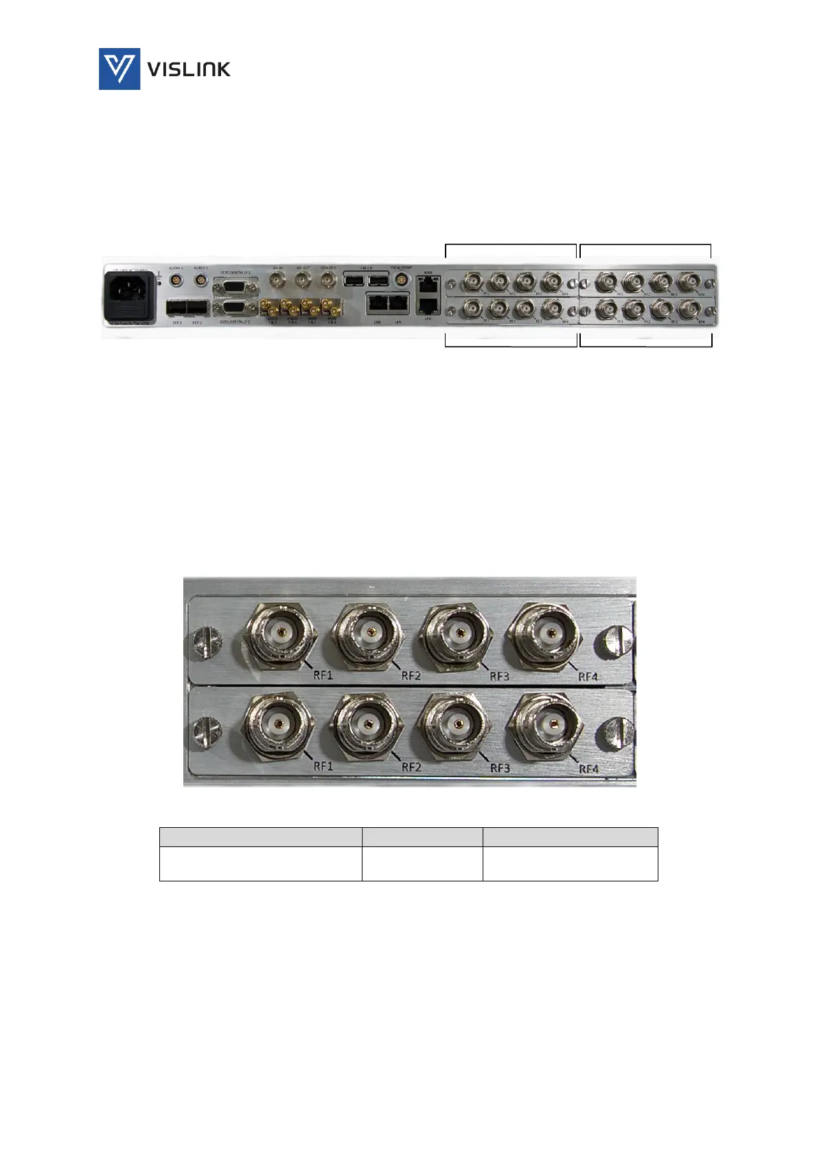
4. Rear Panel Connectors
The unit is designed for rack-mounted use and provides input, output,
monitoring, control and power connectors at the rear panel for connection to
other equipment via cable looms.
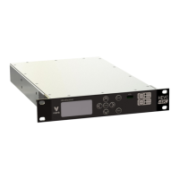
Figure 4-1 Quantum Receiver Rear Panel
4.1. RF Input Connectors (Demod Cards)
Up to four RF Demod plug-in cards may be fitted to the unit. Each of the cards
provides four RF input coaxial connectors for receiving UHF input 70MHz to
860MHz.
NOTE: These inputs can have up to +24VDC output (enabled in Unit/LNB
Power) to power the external down converter; limited to 400mA per
connector, short circuit protected.
Figure 4-2 RF Input Connectors
4x Plug-in Cards, each with
4x RF Connectors:
Table 4-1 RF Input Pinout
4.2. ASI/Genlock Connectors
The Asynchronous Serial Interface (ASI) input and output use copper coaxial
connectors to carry MPEG Transport Streams from/to end equipment. Complies
with ISO/IEC 13818-2 – 188-byte mode. ASI input to the Decoder or packet
diversity function for packet switching (Link Research algorithm).