Quantum Receiver User Manual
Rear Panel Connectors
Issue No: A Page: 19
Ref: ?-Insert_Document_Part_No._Here-? Copyright © 2021 Vislink is a Vislink Technologies Inc. companies
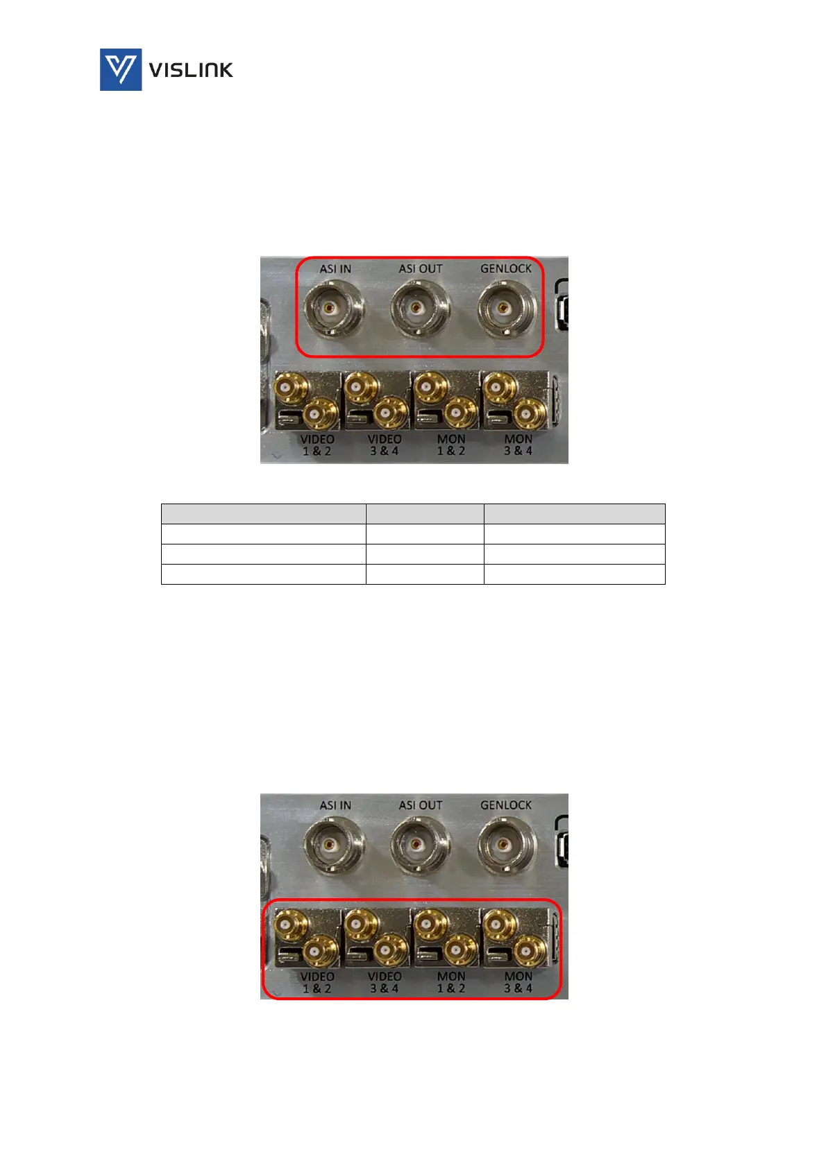
The ASI IN connector routes the received stream to either the video decoder,
packet diversity block or ASI OUT connector.
The ASI OUT connector delivers the output stream from the demodulator,
packet diversity block or ASI input for decoding by an external decoder.
The Generator Locking (Genlock) pulse uses a coaxial connector to synchronize
camera frame capture, accurately aligning video and audio sources.
Figure 4-3 ASI/Genlock Connectors
Table 4-2 ASI/Genlock Pinout
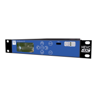
4.3. Video/Monitoring Output Connectors
The unit provides four, small form-factor pluggable (SFP) transceiver modules
used for transmitting Serial Data Interface (SDI) signals up to 2.97Gbps over
75Ω coaxial cables via HD-BNC connectors.
12G SFP option available.
All connectors are outputs (no RX)
Video & Monitor SFPs are non-MSA.
Figure 4-4 Video/Monitoring Output Connectors