EasyManuals Logo

Vislink Quantum User Manual

Vislink Quantum
75 pages
To Next Page IconTo Next Page
To Previous Page IconTo Previous Page
Page #20 background imageLoading...
Page #20 background image
Quantum Receiver User Manual
Rear Panel Connectors
Issue No: A Page: 20
Ref: ?-Insert_Document_Part_No._Here-? Copyright © 2021 Vislink is a Vislink Technologies Inc. companies
Connector
Legend
Description
2x SFP cages:
VIDEO 1 & 2
VIDEO 3 & 4
4x 3G SDI out
2x 6G SDI out
1x 12G SDI out
2x SFP cages:
MON 1 & 2
MON 3 & 4
4x 3G SDI out
2x 6G SDI out
1x 12G SDI out
Table 4-3 Video/Monitoring Output Pinout
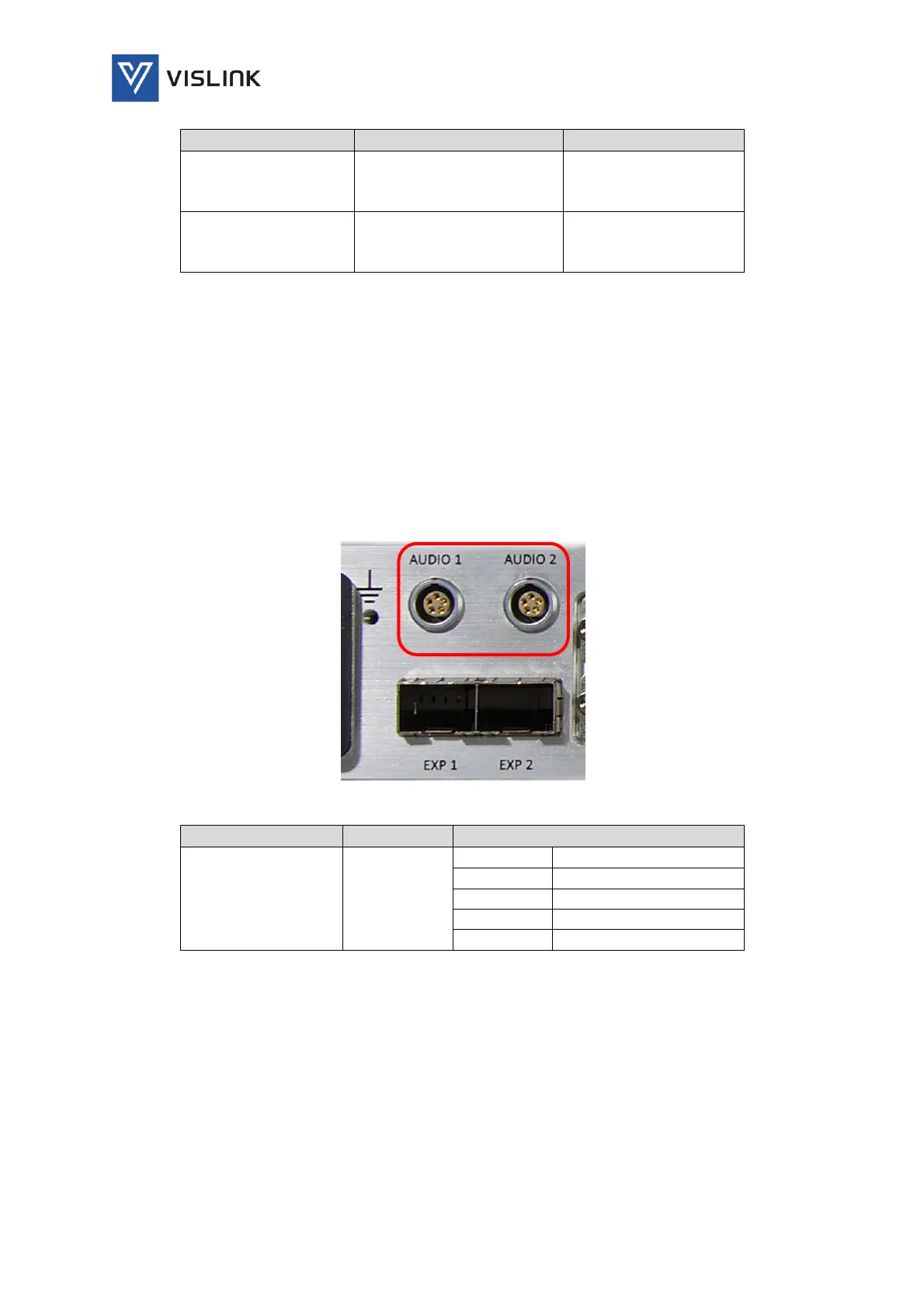
4.4. Audio Output Connectors
Two, 5-pin Lemo connectors with a audio pair per connector (2 x pairs, 4 x
channels).
48kHz sampling
Clip level: 18dB
THD: < 0.1%
20Hz to 18kHz ±0.25dB
Crosstalk: >60dB minimum
Signal to noise ratio: >66dB RMS
Standard cable assembly part number: L0079
Figure 4-5 Audio Connectors
Connector
Legend
Description
2x 5-Pin Lemo
Socket:
AUDIO1
AUDIO2
Pin 1
Left Line + (Line)
Pin 2
Left Line - (Return)
Pin 3
GND
Pin 4
Right Line + (Line)
Pin 5
Right Line - (Return)
Table 4-4 Audio Pinout
4.5. EXP Connectors
Two, small form-factor pluggable (SFP) expansion sockets (MSA SFP 25GbE)
are provided for future expansion of the unit.

Table of Contents

Questions and Answers:

Question and Answer IconNeed help?

Do you have a question about the Vislink Quantum and is the answer not in the manual?

Vislink Quantum Specifications

General IconGeneral
BrandVislink
ModelQuantum
CategoryReceiver
LanguageEnglish

Related product manuals