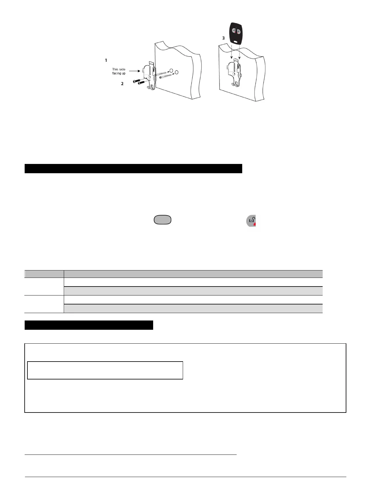
Figure 5 Attaching PB-101/102 to a Wall Mount
1. Using the two screws and plastic anchors included in the PB-
101/102 box, align the holder facing up and secure the holder to the
wall.
2. Slide the PB-101/102 into the holder until you feel it snap securely
inside.
3. To remove the PB 101/102 from the holder, press down the top of
the holder and push the pendant up with your fingers as illustrated in
Figure 2.
4. ENROLLMENT AND CONFIGURATION OF PB-101/102
4.1. Enrollment
The Enrollment process “teaches” the system’s control panel the ID of the PB-101/102 and enables the PB-101/102 to communicate with the panel.
1. Enter the PowerMaster panel’s Installer menu and select “02:ZONES/DEVICES”.
2. Select "ADD NEW DEVICE" Option.
3.
Stand near the PowerMaster panel. Press and hold the button (for PB-101 PG2) or the left button (for PB-102 PG2) until the
yellow LED turns on, and then release the button. Ensure that the LED stays on for 2 seconds and then flashes for 10 seconds.
4.2. Configuring the Panic Button Parameters (for PowerG Version 18 systems only)
Enter the DEVICE SETTINGS menu and follow the configuration instructions for the PB-101 PG2 and PB-102 PG2 panic buttons as described below.
Option Configuration Instructions
Functionality
1
Define whether to use to Arm/Disarm or to operate the PGM.
Optional settings: Arm/Disarm (default) and PGM ON/OFF.
Supervision Define whether the control panel will monitor supervision messages sent by the panic button for a time period of 8hours.
Optional settings: Disabled (default) and Enabled.
5. TESTING AND MAINTENANCE
5.1. Testing a New Unit
Since the PB-101/102 is supplied with the battery already installed, the
unit is practically ready to be tested.
Important! Before testing, enroll the PB-101/102 in the target control
panel as instructed in the panel’s programming instructions.
1. Stand 3 m (10 ft) away from the control panel and press the buttons.
Verify that the transmit LED lights.
2. Make sure that the control panel responds as programmed and as
stated in the panel’s programming instructions.
3. Operate the pendant from various locations within the area covered
by the receiver to determine "dead" locations, where transmission is
blocked by walls and large objects, or affected by structural
materials.
Note: If dead/marginal zones are a problem, relocating the receiver may
improve the performance.
1
Applies to PB-102 PG2 only
D-304457 PB-101 PG2 / PB-102 PG2 Installation Instructions2