QR254 (SERIES) 10
ENGLISH
Installation
WARNING: FUEL (GAS) BURNING RANGES MUST BE VENTED OUTDOORS USING, AT MINIMUM, METAL DUCTWORK AND RANGE HOODS OF SUFFICIENT CAPACITY.
Follow your fuel burning equipment manufacturer’s guidelines, as well as, all applicable safety standards published by the National Fire Protection Association
(NFPA), and the American Society for Heating, Refrigeration and Air Conditioning Engineers (ASHRAE), and your local code authorities.
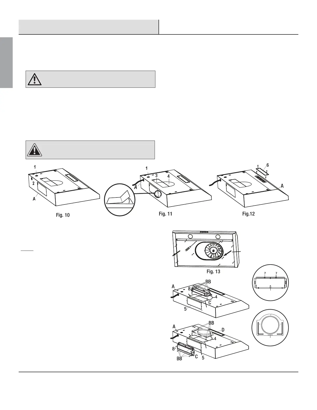
REMOVING THE ELECTRICAL KNOCK-OUT HOLE
:$51,1* Always wear safety goggles and gloves during
installation.
&KRRVHWKHDSSURSULDWHHOHFWULFDONQRFNRXWKROHWRUHPRYHIRU\RXU
installation type. Use the top hole (1) if your electrical supply is in
the cabinet and the back hole (2) if your electrical supply is on the
wall below the cabinet (refer to Fig. 10).
8VHDŶDWKHDGVFUHZGULYHUDQGSOLHUVWRJHQWO\UHPRYHWKHHOHFWULFDO
NQRFNRXWKROH
Use an approved strain relief to ensure the knock out hole does not
damage the insulation of the the electrical supply cable
&$87,21 Please use caution when removing the knock
outs and vent covers to ensure none of the internal
components are accidentally damaged.
REMOVING THE VENTING HOLE
(FOR EXTERIOR VENTING)
Choose the venting hole to remove for your installation type. Use
the top holes (3 & 4) for a top venting installation and the back
hole (5) for a back venting installation. See Installing the damper
section for more details.
Carefully remove the cover (3, 4 or 5) of the appropriate venting
KROHXVLQJDŶDWKHDGVFUHZGULYHURUQHHGOHQRVHSOLHUVUHIHU
Fig. 11). Be care
ful not to damage any internal components when
removing the knockouts and not to leave a
ny debris inside the
range hood (A).
(FOR INTERIOR VENTING)
If you are venting indoors, unscrew the 2 screws holding cover
(6) in place and remove the cover as per Fig. 12. DO NOT REMOVE
ANY OTHER VENTING HOLE COVER.
5
INSTALLING THE DAMPER
(SKIP THIS STEP IF YOU ARE USING INTERIOR VENTING)
Grease Shield
Fig. 14
3B
3A
3A
3B
D
E
NOTE:
Only install the damper if you are using a venting system that does not already have
a damper. If this hood replaces an existing unit, the location of the air exhaust can
YDU\IURPRQHPDQXIDFWXUHUWRDQRWKHU(QVXUHWKDWWKHGDPSHUğWVLQWKHH[LVWLQJ
opening before installing.
The damper and the adapter are located inside the range hood.
To access these parts, remove the grease shield if you have not
previously done so (see Fig. 13).
Choose to install the damper (D) either in the top
position (3A & B) for top venting or in the back position (5)
for back venting. Adapter (E) is used for top venting only and
installs in position 3A and 4.
Attach damper (D) or adapter (E) over chosen knockout opening.
Make sure the damper pivot is oriented on top such that the
damper stays closed when not in use.
Secure the damper (D) or adapter (E) to the range hood (A) with the
short tapping screws (BB).
Seal the damper (D) or adapter (E) to the range hood (A) on all four
sides with duct tape.
 Loading...