HDBaseT 2.0 KVM Extender Set
5
3. System Connection
3.1 Usage Precautions
1) System should be installed in a clean environment and has a prop temperature and
humidity.
2) All of the power switches, plugs, sockets and power cords should be insulated and
safety.
3) All devices should be connected before power on.
3.2 System Diagram
3.3 Connection Procedure
Step1. Connect HDMI source (such as PC) to HDMI IN port of the Transmitter with an
HDMI cable.
Step2. Connect HDBT OUT port of the Transmitter to HDBT IN port of the Receiver
through a straight-thru CAT5e/CAT6 cable.
Step3. Connect a HDMI display to HDMI OUT port of the Receiver with HDMI cable;
Step4. When using the USB control, do the following:
a) Connect PC to the USB OUT port of Transmitter.
USB Signal:
RS232 Signal:
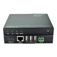
Receiver
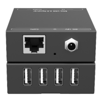
USB IN
Tx Rx
HDBT IN
HDMI OUT
RS232
Transmitter
DC 12V
Tx Rx
RS232HDBT OUTHDMI IN USB OUT
Display
DC 12V
PC
Projector
Esc
Print
SysRq
Screen
Scroll
Lock
Pause
Break
Num
Lock
Caps
Lock
Scroll
Lock
Num
Lock
/
-
+
Enter
7
Home
8
9
PgUp
5
6
1
End
2 3
PgDn
0
Ins
.
Del
~
`
!
1
@
2
#
3
$
4
%
5
^
6
&
7
*
8
(
9
)
0
_
-
+
=
Backspace
Home
Page
Up
Page
Down
Insert
Delete End
Tab
Caps Lock
Shift
Ctrl
Alt Alt
Ctrl
Shift
\
}
]
{
[
:
;
?
/
>
.
<
,
Enter
Q W E R T Y U I O P
A S D F G H J K L
Z X C V B N M
 Loading...