5. Panel Description
5.1 Transmitter
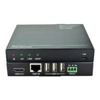
Turns red when DC power present.
Turns green when the transmitter and receiver link
successful.
Turns green when the signal data is transmitted between
transmitter and receiver.
▪ ARC (Default): Switch the audio mode to ARC.
▪ AUDIO: Switch the audio mode to AUDIO.
The DIP switch must be worked with another switch on
receiver, for more details, please refer to the 6.system
connection.
USB port, used for firmware update.
Connect to the OPTICAL IN port on receiver via two fiber
cables (A-B; B-A).
Connect to audio broadcast device.
Work with far-end IR OUT port on receiver, connect to IR
receiver (with carrier) to collect IR signal to control far-
end display.
Work with far-end IR IN port on receiver, connect to IR
Emitter to send IR signal to control source device.
Makes up bi-directional RS232 pass-through control with
the RS232 port on receiver. If one is connected to control
device (e.g. PC), and the other should be connected to
the third-party that need to be controlled.
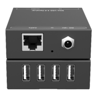
Connect to 12V DC power adaptor.
 Loading...