EN - 6
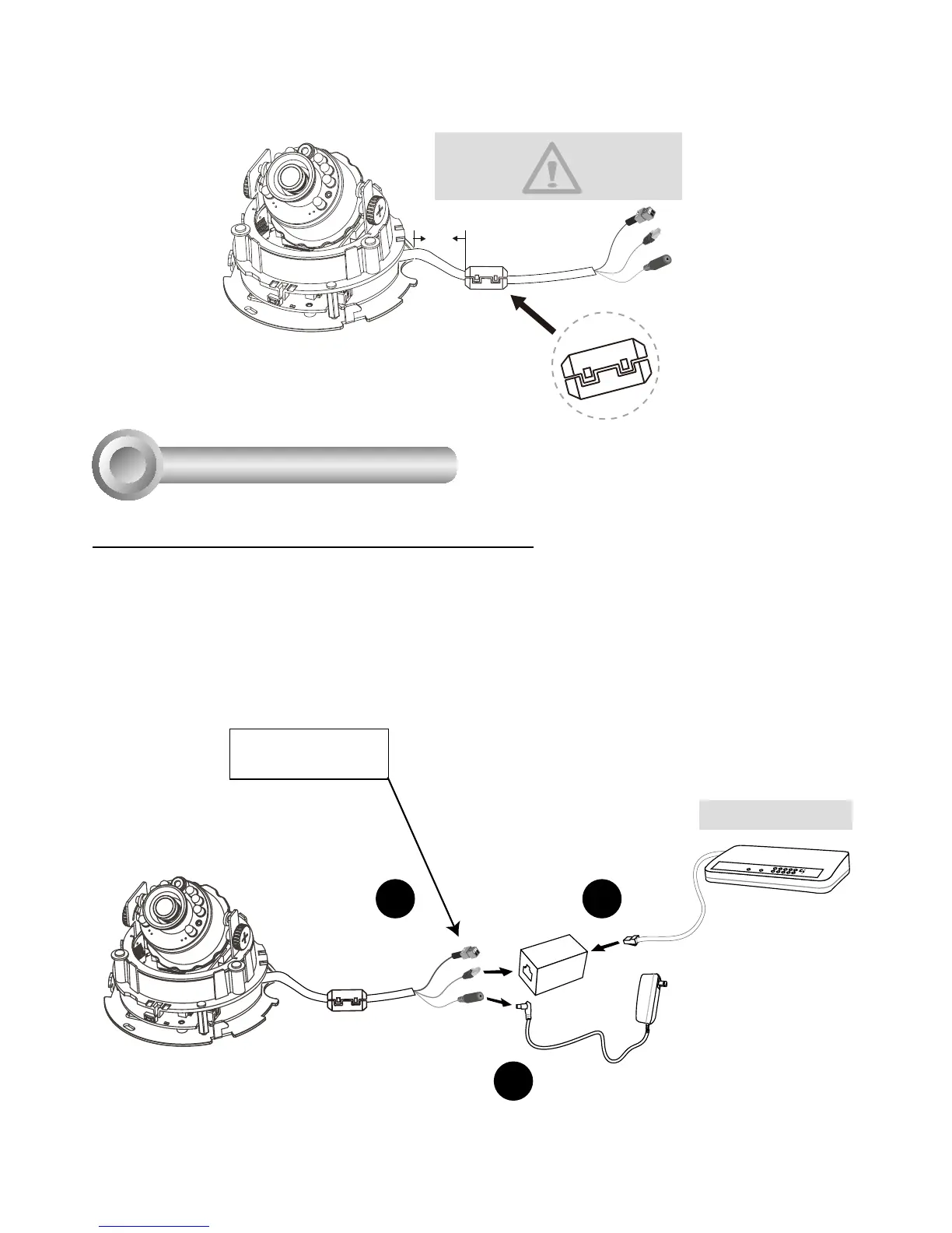
General Connection (without PoE)
Network Deployment
4
+ : Digital input
- : Digital input
POW
ER
C
O
LL
I
S
ION
L
I
N
K
RE
CEIVE
PARTITIO
N
1
2
3
4
5
2
3
Ethernet Switch
1
1. If you have external DI devices, make the connection from general I/O terminal block.
2. Use the supplied RJ45 female/female coupler to connect the Network Camera to a
switch.
Use a Category 5 Cross Cable when Network Camera is directly connected to PC.
3. Connect the supplied power cable from the Network Camera to a power outlet.
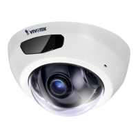
6. Buckle the supplied clamp core onto the cable to against the EMI radiation.
5 cm
The clamp core should be away
from the device at least 5 cm.

 Loading...