EasyManuals Logo

Vivotek FD8366-V User Manual

Vivotek FD8366-V
360 pages
To Next Page IconTo Next Page
To Previous Page IconTo Previous Page
Page #8 background imageLoading...
Page #8 background image
VIVOTEK
8 - User's Manual
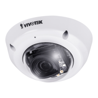
3. If using the optional combo cable, the DI wires and Ethernet cable are pre-congured
with a waterproof rubber seal. If preferred, connect the DI pins to external sensor
devices.
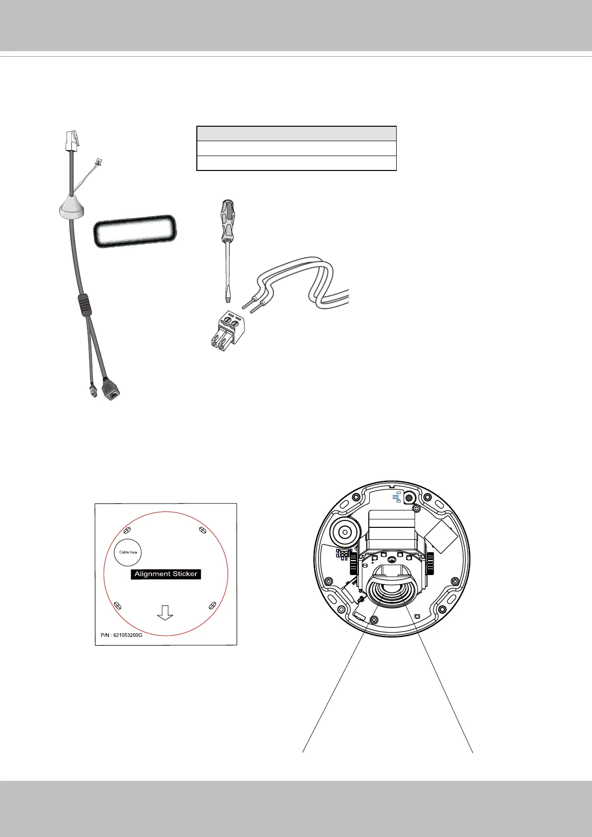
4. Attach the alignment sticker to a preferred location. Aim the shooting direction on the
sticker at a direction you prefer. Drill holes on the wall or ceiling to install the plastic
anchors. Anchors may not be necessary for installation on different materials.
Name
DI+ (any input <30V)
DI- GND
Optional

Other manuals for Vivotek FD8366-V

Questions and Answers:

Question and Answer IconNeed help?

Do you have a question about the Vivotek FD8366-V and is the answer not in the manual?

Vivotek FD8366-V Specifications

General IconGeneral
BrandVivotek
ModelFD8366-V
CategorySecurity Camera
LanguageEnglish

Related product manuals