VIVOTEK
User's Manual - 23
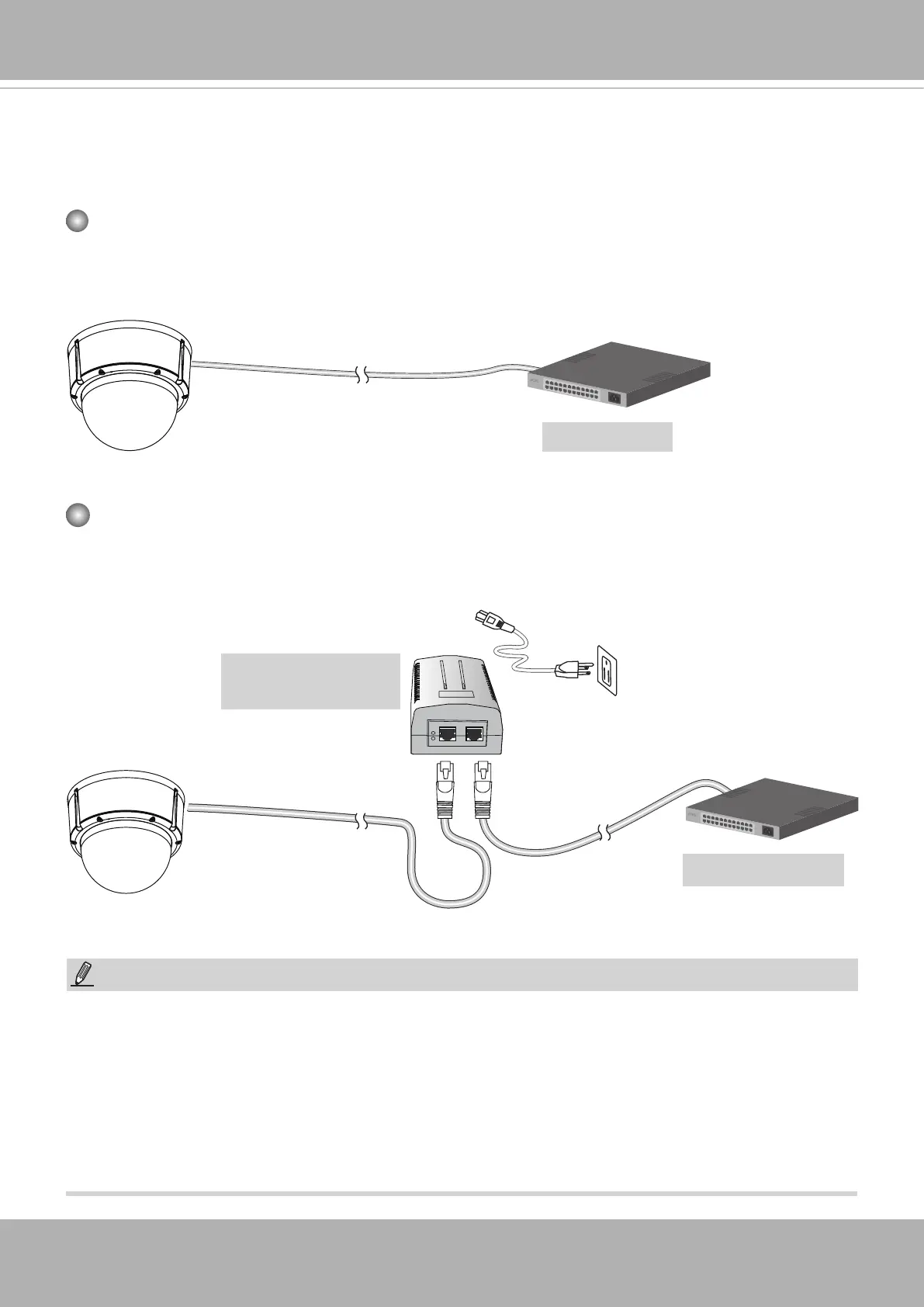
Network Deployment
General Connection (PoE)
When using a PoE-enabled switch
The Network Camera is PoE-compliant, allowing transmission of power and data via a sin-
gle Ethernet cable. Follow the below illustration to connect the Network Camera to a PoE-
enabled switch via Ethernet cable.
PoE Switch
When using a non-PoE switch
Use a PoE power injector (optional) to connect between the Network Camera and a non-
PoE switch.
Non-PoE Switch
PoE Power Injector
(optional)
NOTE:
1. The camera is only to be connected to PoE networks without routing to outside plants.
2. For PoE connection, use only UL listed I.T.E. with PoE output.
1. La caméra ne doit être raccordée qu’à des réseaux PoE, sans routage vers des installations
extérieures.
2. Pour les raccordements PoE, utilisez uniquement un équipement de TI homologué UL, avec une sortie
PoE.
802.3at
802.3at