- 2 -
www.vivotek.com
T: 886-2-82455282
F: 886-2-82455532
self-test, go to next paragraph “Software installation”. If the Ethernet is not available,
Network Camera will switch to wireless LAN mode.
To install in wireless LAN
If the Ethernet is not available while power on, the Network Camera will search for any
access point with the SSID “default”. Once any access point is found, the LED will turn
green to wait for installation. If the network environment cannot meet the default
settings, install Network Camera in Ethernet to proceed with wireless LAN
configuration.
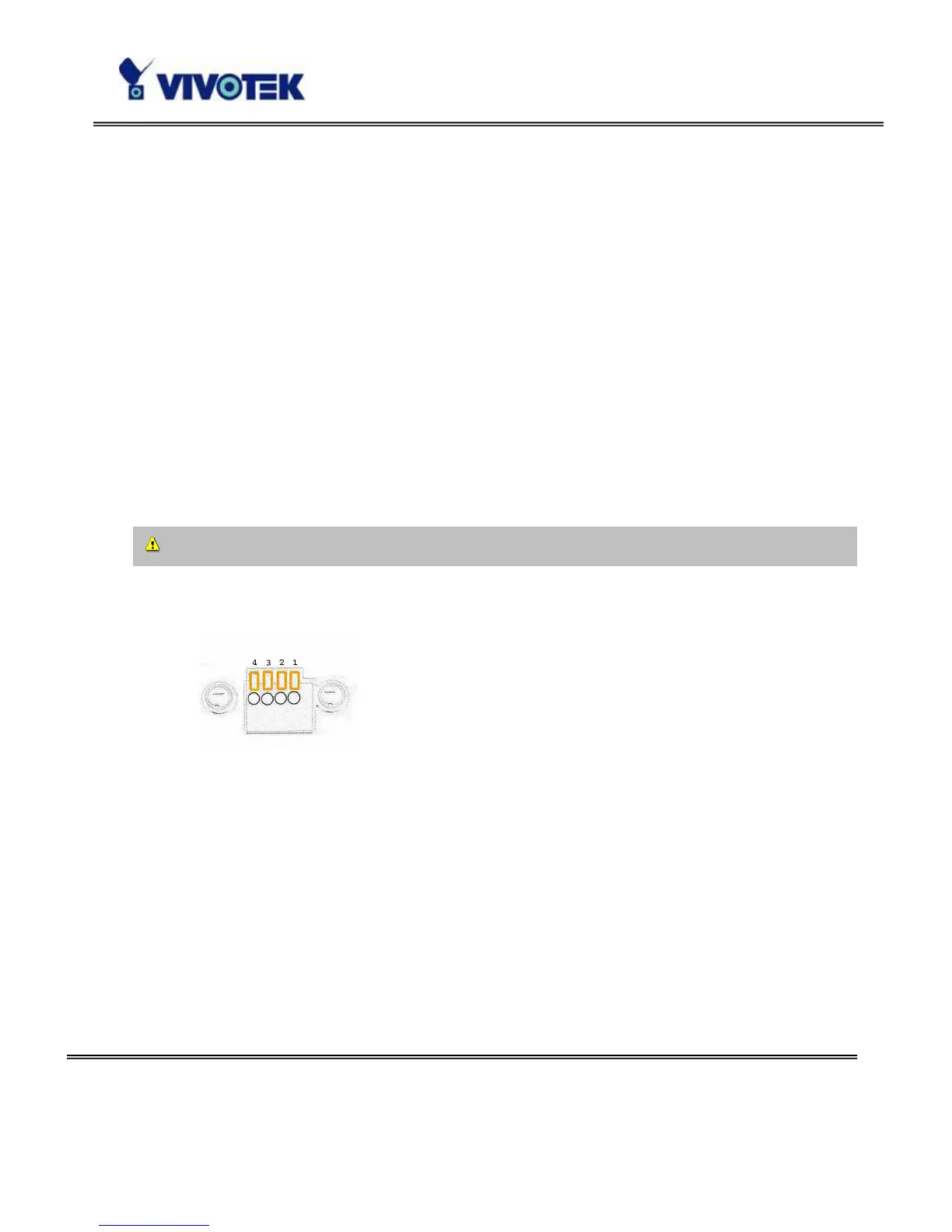
The Network Camera provides a general I/O terminal block with one digital input and
one relay switch for device control. Pin 1 and Pin 2 can be connected to an external
sensor device and the state of voltage can be monitored from the initial state 'LOW'.
The relay switches Pin 3 and Pin 4 can be used to turn on or off an external device.
Consult with the dealer of the peripherals for correct installation.
1 DI+ INPUT (Max. 50mA, 12VDC)
2 DI- INPUT (Initial state of DI is Low)
3 SW_COMMON OUTPUT (open from SW_OPEN at initial state)
(close with SW_OPEN when DO is set to ON)
4 SW_NOPEN OUTPUT (Max. 1A, 24VDC or 0.5A, 125VAC)