EN - 3
English
Hardware Installation
3
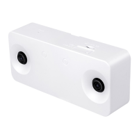
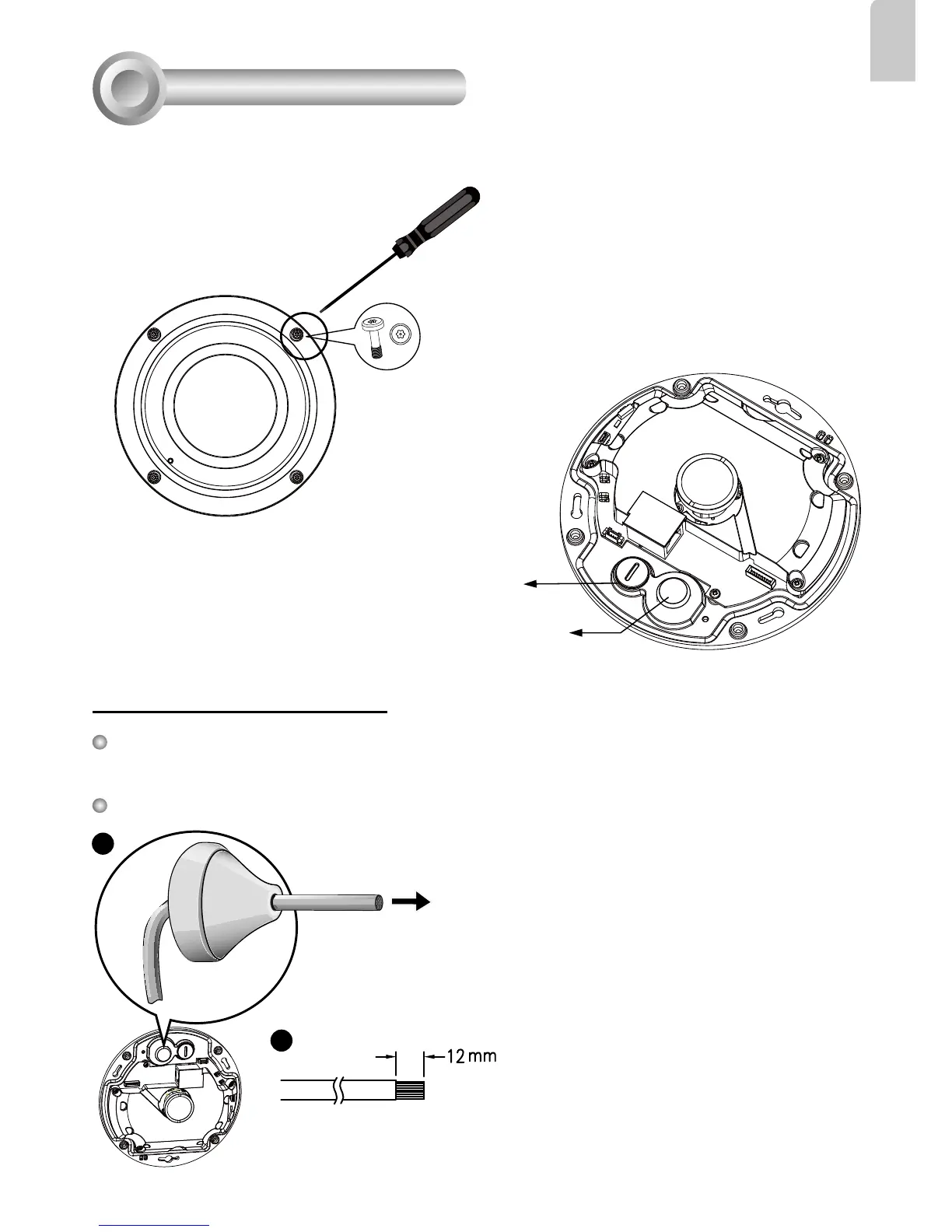
Rubber Stopper on the hole for
Power & IO Cables
Tamper-proof Screw
Rubber Seal Plug on the hole
for RJ45 Ethernet Cable
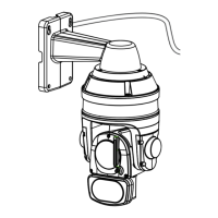
First, use the supplied screwdriver to loosen the four screws and detach the dome cover from the
camera base. Then, follow the steps below to install the camera to either a ceiling or a wall.
Remove the stoppers and route cables through the
openings.
2. Strip part of the sheath from the Ethernet
cable.
1. Drill a hole on the rubber seal plug and insert
an Ethernet cable through the opening.
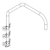
Connecting RJ45 Ethernet Cable
RJ45 Cable Dimension (unit: mm)
Recommended cable gauge: 24AWG (0.51 mm)
Assembly Steps
Rubber Seal
Plug
1
2