EN - 8
Network Deployment
30~100cm
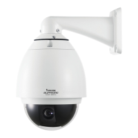
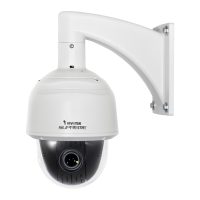
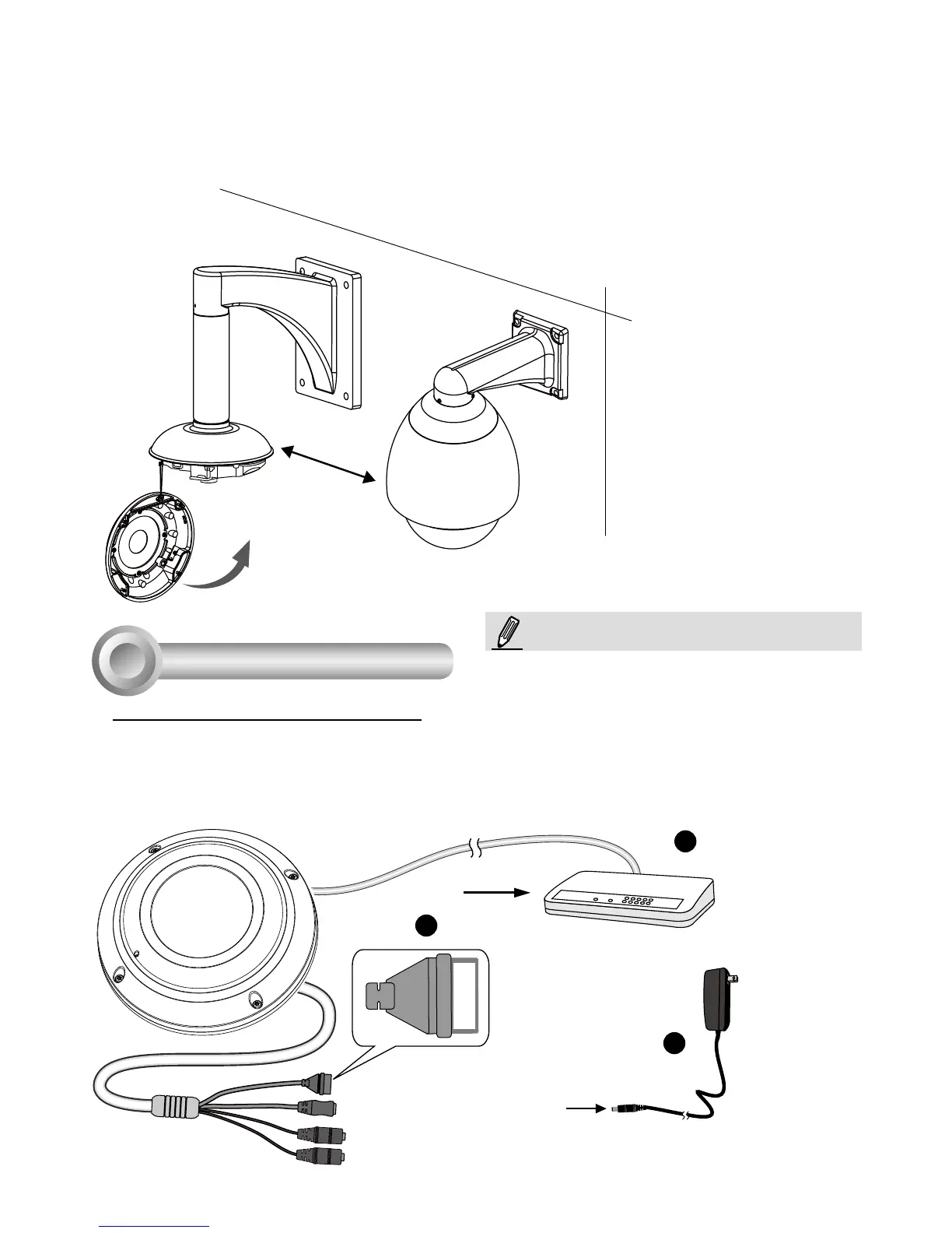
7. Install the speed dome camera next to the fisheye, with their lens positioned at approximately the
same height. For details about speed dome installation, please refer to its documentation.
8. Connect all cabling, including the IO cables to J6 and J7, and the Ethernet cable to RJ-45 connector.
9. Install the dome cover by fasteninng the anti-tamper screws.
General Connection (without PoE)
1. Connect RJ45 Ethernet cable to a switch.
2. Connect the power cable from the Network Camera to a power outlet.
3. If you have external devices such as sensors and alarms, make the connection from the general
I/O terminal block.
4
POW
ER
C
O
LL
I
S
ION
L
I
N
K
RECEIVE
PARTITIO
N
1
2
3
4
5
+3V3
DO
D1
GND
1
2
3
General I/O Terminal Block
Power Cord Socket (Black)
Microphone In (Pink)
Audio Out (Green)
+3V3: Power, 3.3V DC
DO: Digital Output
D I: Digital Input
GND: Ground
NOTE:
If DC power is preferred, it should comply with: O/P:
12VDC, 1.5Amin., L.P.S. per IEC 60950-1.