VIVOTEK
User's Manual - 7
o
O
g
B
b
G
br
BR
1
2
3
4
5
6
7
8
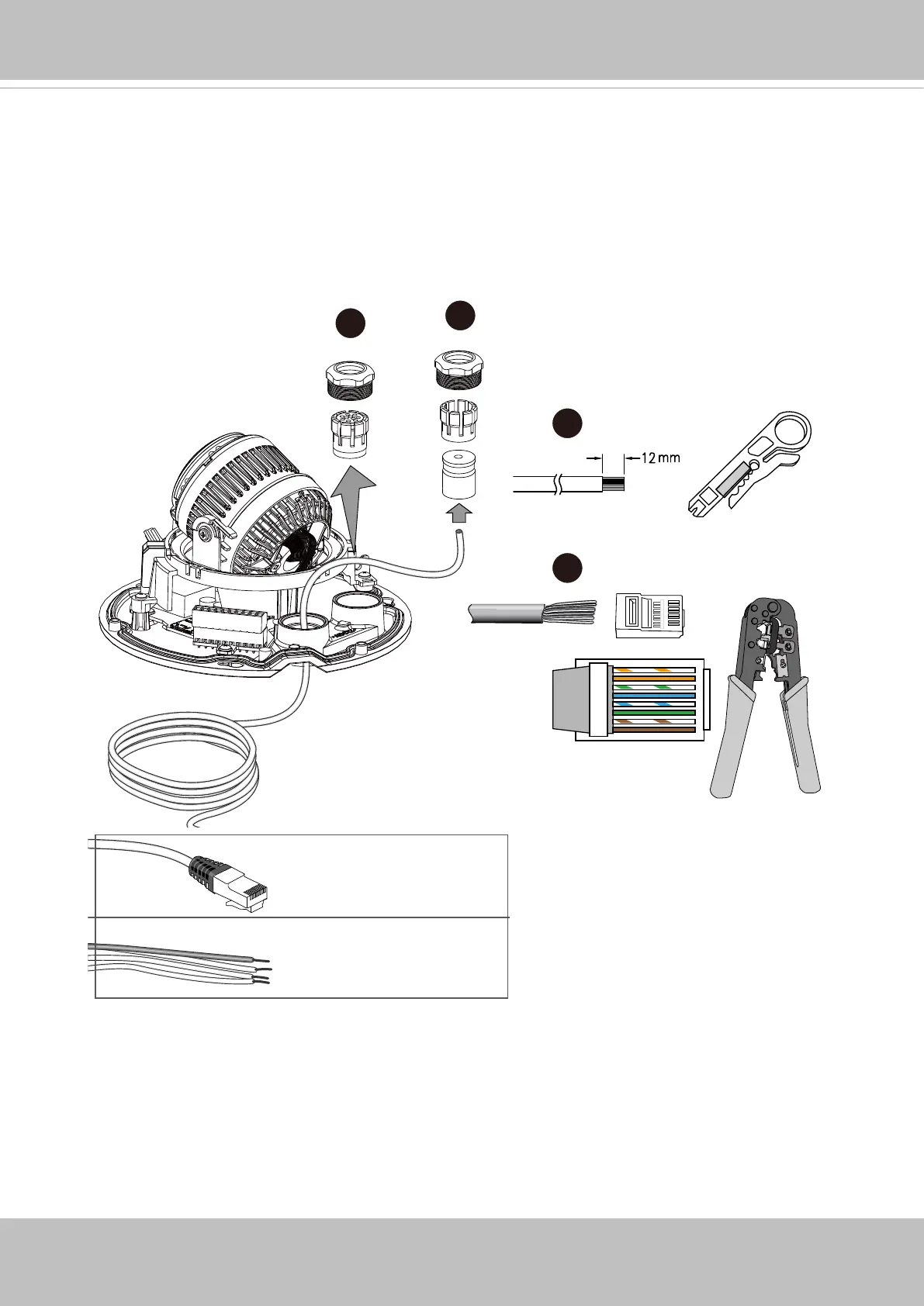
o: white/orange stripe
O: orange solid
g: white/green stripe
B: blue solid
b: white/blue stripe
G: green solid
br: white/brown stripe
BR: brown solid
5~6.3mm
DI/DO: 1.8~2.1mm
3
4
5
6
3. Loosen and remove the waterproof connectors.
4. Insert an Ethernet cable through the cable gland, and the rubber seal.
5. Remove part of cable sheath.
6. You will need an RJ45 crimping tool to attach the Ethernet wires to a connector. When
done, connect the cable to the camera’s Ethernet RJ45 socket.