57
[2]POWER SCHEMATIC DIAGRAM
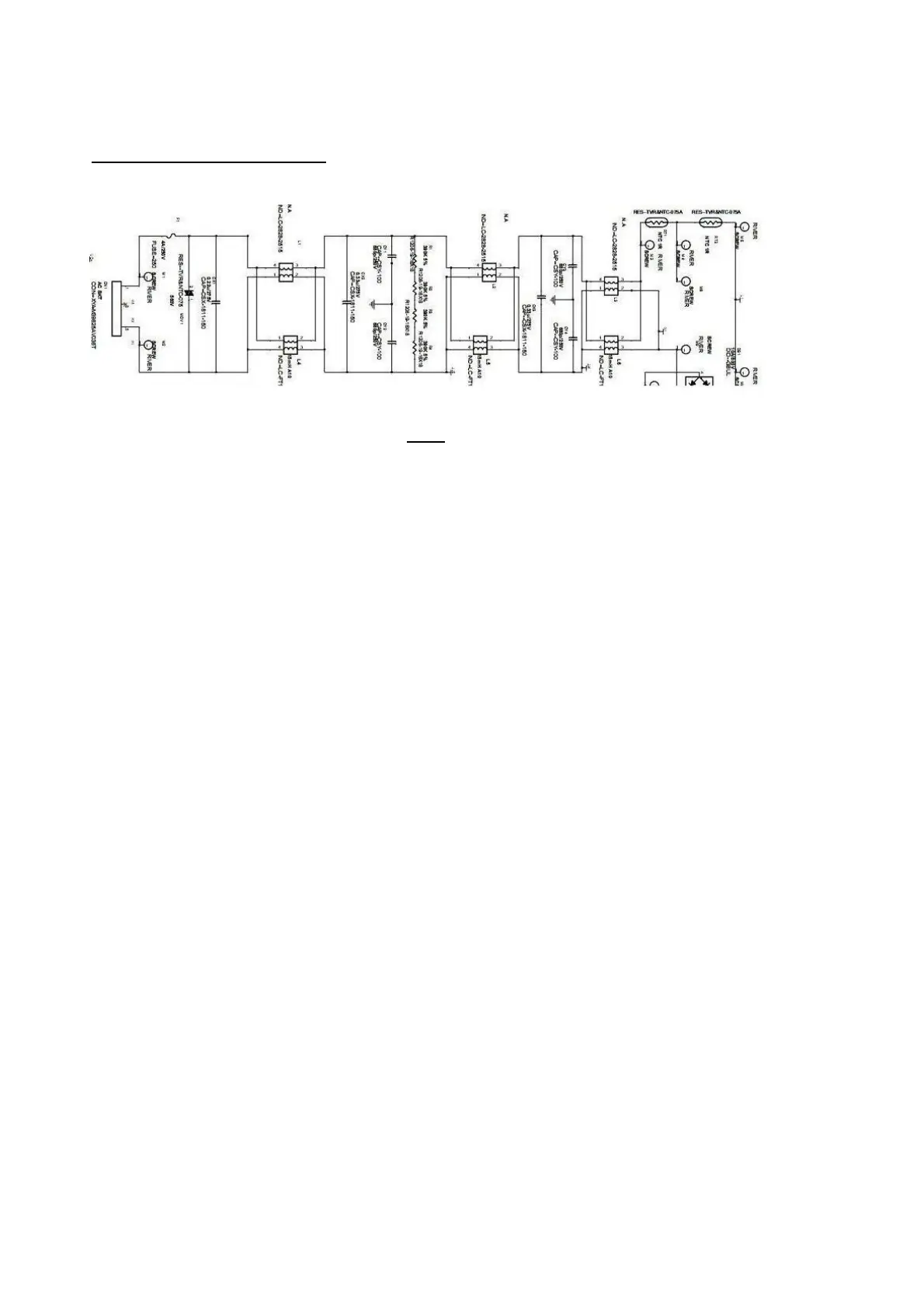
1) AC Input and EMI Filter:(fig.7)
Fig.7
CN1 is a connector for connecting AC Power.F1 is fuse to protect all the circuit AC. Input
voltage is single 110V. CY1, CY2, CY3, CY4 are used high frequency noise of primary between
common GND.L4,L5,L6,CX1, CX2 is used to filter low frequency noise. R1,R2,R3,R4 are used to
discharge CX1 and CX2 remnants voltage.
DB1 is a rectifier in which there are 4 build-in diodes, inverting AC to DC. C101 is used to
smooth the wave from rectifier. RT1 & RT2 is a fuse resistor to protect the following circuit when
inrush current is too large.
 Loading...