Control Unit KTM60 M0
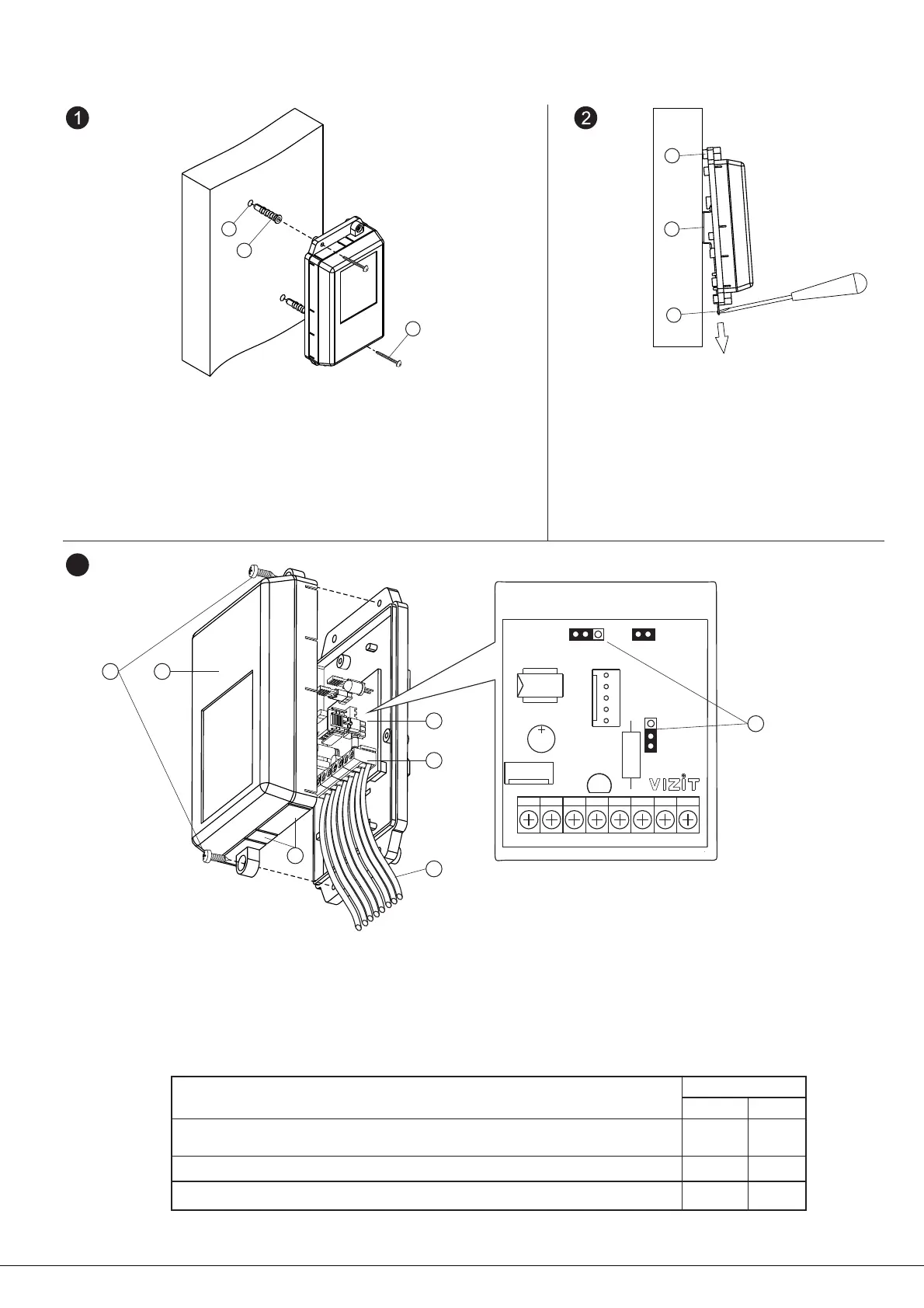
The Control Unit may be mounted either on a wall, or a DIN-rail.
-
- (4) coming from the power supply unit, Reader RD-4F, EXIT 300M button and lock.
- Connect the ends to the C U ’s terminals 5
- S (6) on the C U ’s PCB (7)
ontrol nit ( )
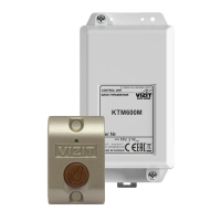
et jumpers ontrol nit according to the table :
U C U ’s cover (2)
nfasten two screws (1) and take off the ontrol nit .
Cut the plastic parts 3 off the cover.
Strip the ends of connecting wires
-()
EXAMPLES OF WIRING
DIAGRAMS
following the diagrams given in the section
.
3
Lock Type
Jumper
Fail-locked strike / lock (12 VDC / 1 A max.)
LOCK
ML
TIME
7s
Electromagnetic lock
Fail-unlocked strike / lock (12 VDC / 0.6 A max.)
VIZIT
Fail-locked strike / lock with hold-open function (12 VDC / 1 A max.)
EL
7s
EL
1s
3
1
2
4
5
6
- Drill 2 holes (1) in a wall, with diameter 6 mm and depth mm
- Drive anchors (2) into the holes
Attach the Control Unit to the wall and fasten screws 4x40
in the anchors
Note. Anchors and screws are supplied
.
.
- 2 (3)
.
.
40
( ) Bosses on the Control Unit’s base
( ) rail with width mm and
thickness mm
( ) Holder for fixing
1-
2 - DI - 35
1-2
3-
N
1
2
3
1
2
3
KTM600M mounting on a railDIN-KTM600M mounting on a wall
ML
EL
PRG
1S 7S
-DL
+DL BIP+E RDGND RG OP
7
www. 5VIZIT-KTM600F Operating Instruction (revision 10)vizit-group.com 8 11/201 -