* Terminal 37 is not included in FC 301 (except frame size
A1). Relay 2 and terminal 29 have no function in FC 301.
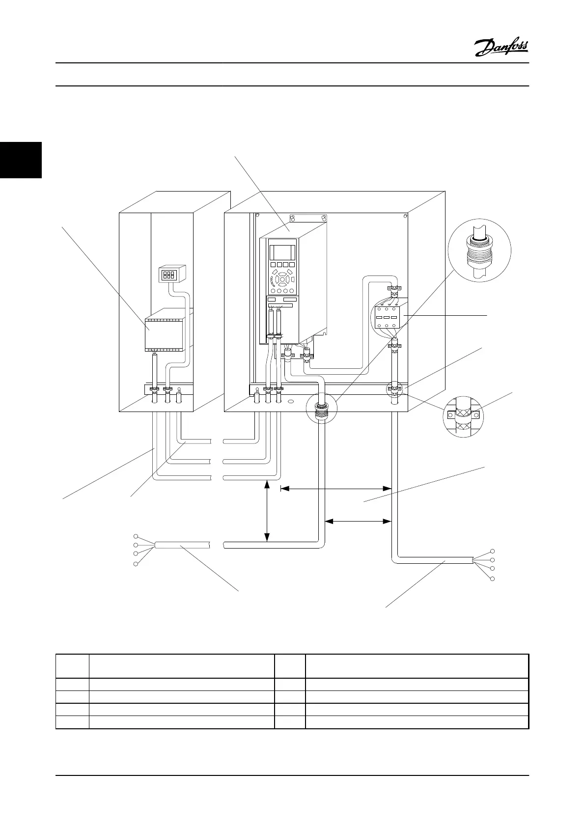
** Do not connect cable screen.
1
2
3
4
5
6
7
8
PE
U
V
W
9
L1
L2
L3
PE
130BB607.10
10
Figure 2.5 Typical Electrical Connection
1
PLC 6 Min. 200 mm (7.9 in) between control cables, motor and line
power
2 Adjustable frequency drive 7 Motor, 3-phase and PE
3 Output contactor (Generally not recommended) 8 Line power, 3-phase and reinforced PE
4 Grounding rail (PE) 9 Control wiring
5 Cable insulation (stripped) 10
Equalizing min. 16 mm
2
(0.025 in
2
)
Table 2.2 Legend to Figure 2.5
Installation
VLT
®
AutomationDrive Instruction
Manual
2-4 MG33AM22 - VLT
®
is a registered Danfoss trademark
2
2