2-6 Vogt
®
VT Service Manual
Installation Instructions
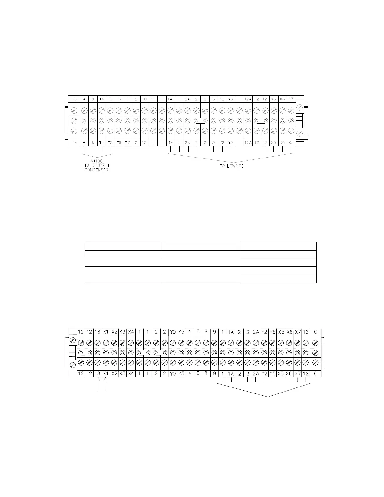
Air Cooled Condenser Wiring (VT100 with KeepRite Condenser) :
Run four #14 AWG wires
from the terminals A, B, T4 and T5 on the condensing unit control panel terminal block to the air cooled
condenser control panel.
FIGURE 2-5
Condensing Unit Terminal Blocks
Lowside Electrical Connections:
Run 11 #14 AWG or larger wires run from the Lowside control panel
terminal block to the condensing unit (highside) control panel terminal block.
TABLE 2-6
Lowside to Highside Wire
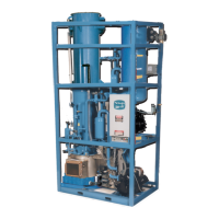
FIGURE 2-6
Lowside Unit Terminal Block
Note: Machine is supplied with a remote “on/off” connection on the lowside terminal block. If a remote
“On/Off” switch is used, remove jumper between #18 & #X1 and connect switch to these terminals.
(AWG)
5 16 (Red) 1, 2, 3, Y2, Y5
4 16 (Blue) X5, X6, X7, 12
2 14 (Black) 1A, 2A
1 14 (Green) GND
Standard Voltage Machine
200/230V or 400/460V, 3PH, 50/60HZ
REMOTE “ON/OFF” SWITCH
TO LOWSIDE