Instruction and Operating Manual
Overspeed Protector CTO-B45202
J.M. Voith SE & Co. KG │ Division Digital Ventures
3 Function
3.1 Mechanical design
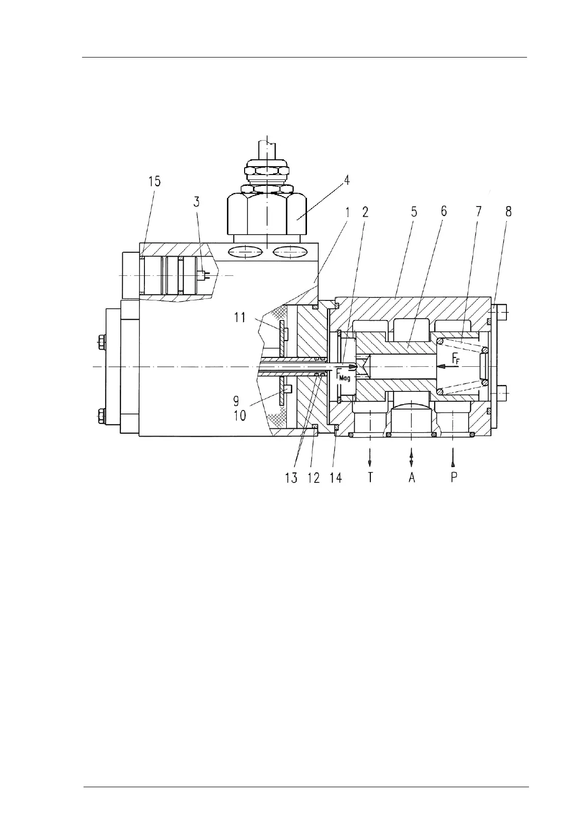
Fig. 1: Sectional view of overspeed protector
The overspeed protector consists of the main functional units:
(1) Control magnet VRM P - supply pressure
(2) Tappet for power transmission A - output
(3) Potentiometer T4 T - Tank return line
(4) Electrical connection
(5) Control housing
(6) Control piston F
Mag
- Magnetic force
(7) Restoring spring F
F
- Federkraft
(8) Cover
(9) Potentiometer Uf
(10) Potentiometer If
(11) 8-fold coding switch
(12) Sealing - electronic compartment cover
(13) Sealing - pole pipe
(14) O-ring for the VRM
(15) O-ring in the potentiometer cover