Do you have a question about the Voith VR 115 E and is the answer not in the manual?
Explains the manual's scope and content.
Identifies intended audience and usage restrictions.
Lists related documents for further reference.
Explains warning symbols and identification methods.
Describes how item numbers are used in spare parts lists.
Provides contact details for inquiries and support.
Details safety aspects of the retarder's construction.
Specifies requirements for personnel performing work.
Outlines general safety principles and regulations.
Covers proper disposal of fluids and parts.
Advises on warranty service and avoiding speculative part replacement.
Warns about hot oil, coolant, and parts during work.
Ensures retarder functionality for safe vehicle operation.
Explains liability limitations for modifications and unauthorized parts.
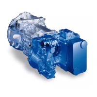
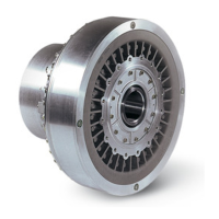
Identifies and illustrates key components of the retarder.
Explains how to identify the retarder using serial and item numbers.
Details identification data for the VERA™ controller.
Details identification data for the Digiprop controller.
Illustrates the pneumatic and control system layout.
Explains the operation of individual components and systems.
Outlines recommended intervals for maintenance activities.
Provides detailed steps and specifications for changing retarder oil.
Describes the procedure for verifying the retarder oil level.
Details the process for draining the coolant from the system.
Guides users through identifying and resolving common issues.
Explains how to test and diagnose the control loop.
Details the procedure for measuring and checking pump pressure.
Describes how to measure and check the proportional valve current.
Explains how to measure and calculate the correct shim thickness.
Provides step-by-step instructions for installing the retarder.
Shows an exploded view and lists all retarder components.
Details the removal and installation of the top oil tank cover.
Details the removal and installation of the bottom oil tank cover.
Describes how to remove, check, and install casing ventilation components.
Explains how to check, clean, and replace the retarder ventilation.
Details the removal and installation of the water neck.
Provides steps for removing, checking, and installing the heat exchanger.
Details the removal, checking, and installation of the pressure control valve.
Describes the removal, checking, and installation of the non-return valve inlet.
Details the removal, checking, and installation of the non-return valve outlet.
Explains how to check the resistance of the oil temperature sensor.
Explains how to check the resistance of the coolant temperature sensor.
Details the replacement procedure for the pressure sensor.
Describes the components and checks for the proportional valve and damping plate.
Lists torque specifications for various components.
| Brand | Voith |
|---|---|
| Model | VR 115 E |
| Category | Industrial Equipment |
| Language | English |