Page 17
Function and Control SchemeVoith Turbo I Aftersales Service Manual Voith Retarder VR 115 E I Design and Function
Voith Turbo I 153.00009710 I arrtd I 2005-11
© 2005
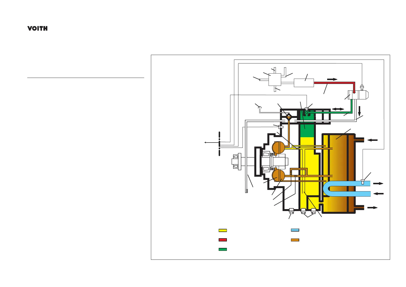
3.5 Function and Control Scheme
Item No. Designation
A Compressed-air line (pressure
controller)
B Four-circuit protection valve
C Compressed-air line (brake circuit 2)
D Compressed-air line (brake circuit 1)
E Compressed-air line (parking brake)
F Air tank for auxiliary equipment
G Supply-air pressure (p
v
) "P"
H
Constant-air pressure (p
y
) "A"
I Ventilation line "R"
J Oil tank
K Rising duct
107 Oil drain plug
200 Stator
300 Rotor
1900 Non-return valve (inlet)
2100 Non-return valve (outlet)
2200 Pressure control valve
A
R
P
H
G
2300
I
6400
5200/2
1900
5200/1
300
5500
200
2200
4200
107
2100
2810
3700
J
K
9000
A
B
C
D
E
F
28005
Vehicle
electronics
Oil sump
Supply-air pressure p
v
Constant-air pressure p
y
Coolant
Pump pressure p
dyn