23 – Supply system - mechanical injection (diesel)
1 Maintaining the direct injection Diesel
system
The direct injection diesel system command unit has a fault mem‐
ory. Before performing repairs, and for fault location, refer to the
fault memory ⇒ page 115 .
Safety measures ⇒ page 107 .
Cleaning rules ⇒ page 107 .
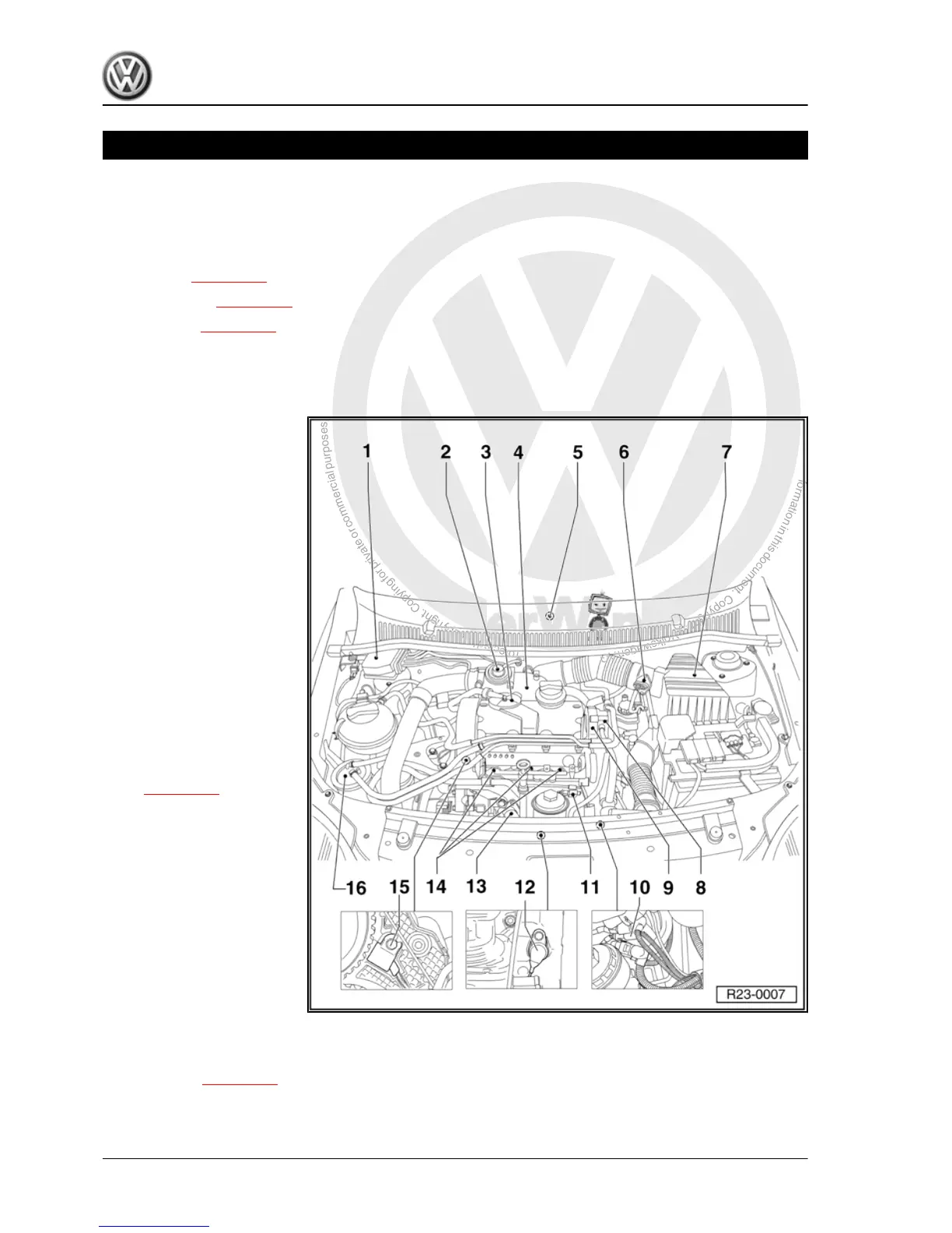
1.1 Installation locations - overview
Components A to D are not shown in the illustration.
A - Brake pedal switch -F47- or
Brake light switch -F-
❑ Together in one case, in
the feet compartment,
on the brake pedal.
B - Accelerator pedal position
sensor -G79- and Sensor 2 of
accelerator pedal position -
G185-
❑ At the feet compart‐
ment, on the accelerator
pedal.
C - Clutch pedal switch -F36-
❑ In feet compartment, on
clutch pedal.
D - Fuel pressure regulator
❑ In fuel pump.
1 - Valve blocking
❑ Vacuum hose connec‐
tion diagram
⇒ page 121 .
2 - Exhaust gas recirculation
valve (mechanical)
❑ With intake manifold
valve.
3 - Pressure regulating valve
❑ To crankcase vent.
4 - Intake manifold
❑ Intake manifold pres‐
sure sensor -G71- with
Intake manifold temper‐
ature sensor -G72- .
5 - Direct injection diesel sys‐
tem control unit -J248-
❑ With Altitude sensor -F96- .
❑ Replace ⇒ page 115 .
Fox 2004 ➤
3 - Cyl. diesel engine - Edition 02.2009
106 Rep. Gr.23 - Supply system - mechanical injection (diesel)

 Loading...