28
OPERATING ELEMENTS
See fold-out page
1. HOLD button
2. Non-contact voltage sensor
3. Torch light (Only on VC155)
4. LC display
5. Rotary switch
6. Battery compartment
7. Stand clamp
8. VΩ socket (VC135) / mA µA ºCΩV socket (VC155)
9. COM socket (reference potential)
10. 10A max socket (Only on VC155)
11. Torch button (Only on VC155)
12. BACK LIGHT button (Only on VC155)
DISPLAY INDICATIONS AND SYMBOLS
Battery replacement icon; please replace the battery as soon as possible
Symbol for the diode test
Lightning icon for voltage measuring (VC155 only)
Symbol for the acoustic continuity tester
~ AC Alternating current
DC Direct current
Symbol for active hold function
Ω Ohm (unit of electric resistance)
ºC Unit of temperature
OPERATION
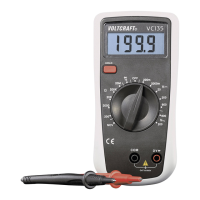
The multimeter (referred to as DMM in the following) indicates measured values on the digital display.
The measuring value display of the DMM spans 2000 counts with VC135 (count = smallest display
value). The measuring device can be used for do-it-yourself or for professional applications (up to
CAT III 600 V). For better readability, the DMM can also be mounted with the clip on the rear.