41
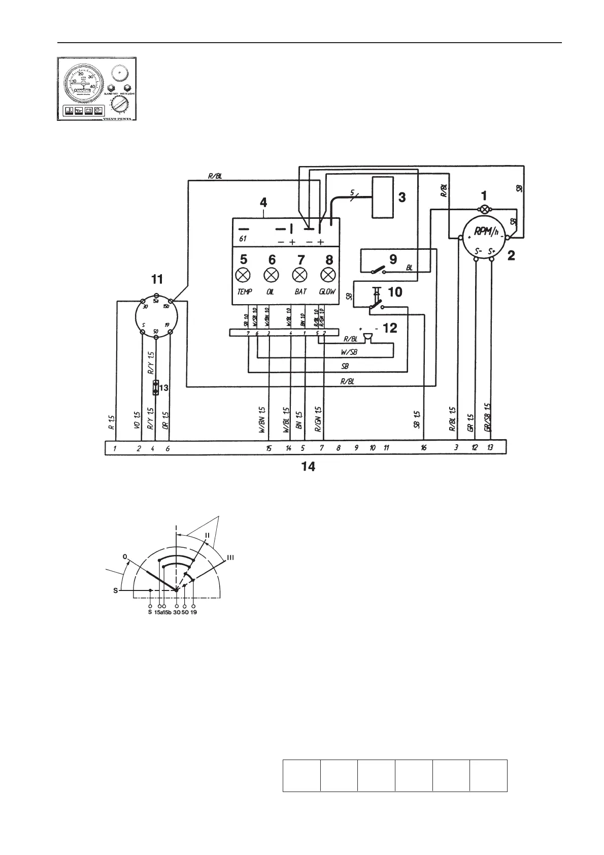
Wiring Diagrams
Instrument panel with ignition switch (Alt. 1)
1. Instrument lighting
2. Tachometer with built-in hours
run meter (accessory)
Dummy plug
3. Connector for connecting extra
warning display (accessory)
4. Electronics module (alarm)
5. Engine coolant temperature
warning lamp
6. Oil pressure warning lamp
7. Charge warning lamp
8. Glow plug indicator lamp
9. Switch, instrument panel ligh-
ting
10. Alarm test/acknowledgment
switch
11. Ignition switch
12. Alarm
13. Connector for neutral position
switch, if fitted (accessory)
14. 16-pin connector
Spring back
Spring back
Cable color
BL = Blue
BN = Brown
GN = Green
GR = Gray
OR = Orange
R = Red
SB = Black
VO = Violet
W = White
Y = Yellow
Cable areas in mm
2
are indicated after the color codes in the
wiring diagrams.
Areas not indicated = 1.0 mm
2
.
Conversions mm
2
/AWG*
*American Wiring Gauge
mm
2
1.0 1.5 2.5 10 16
AWG 16 (17) 15 (16) 13 7 5
7738231 - Downloaded from www.volvopenta.com 29/03/2009 14:51:17