14
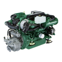
LEDs (digital trim instruments)
1 Flashes red in tilt range above 40. Otherwise off.
2 Continuous red light: Range 6 through 40. Other-
wise switched off.
3 Continuous green light: Range 2 through 5. Oth-
erwise switched off.
4 Continuous green light in the range 0 through 2.
Otherwise switched off.
5 Continuous green light in trimmed position th-
rough 0. Otherwise switched off.
6 Continuous yellow light in max. trimmed position
through 0. Flashes when drive moves and the
bow is lowered. Otherwise switched off.
7 Continuous yellow light: Range 2 through 5.
Flashes when the drive moves and the bow is
raised.
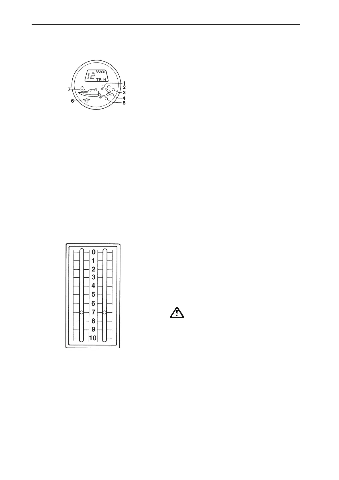
The trim indicator, which is mechanically controlled,
displays the drive position in the trim range as a di-
git from 0 to 7. Check during the first test drive
which trim position provides the best comfort and
then use this number as a starting position in the fu-
ture.
When the drive is in the Beach range, 7-10, the
speed must be lower than planing speed. The engi-
ne must be stopped when fully tilted.
The trim indicator displays the position in the trim
range and the beginning of the Beach range only. In
the case of a double installation, individual trimming
of the drives is permitted in the trim range. Take
note of the trim indicators.
WARNING ! If the drive needs to be tilted
in the Beach range, both drives must be til-
ted at the same time (i.e. parallel) to pre-
vent unnecessary stress on the tie rod bet-
ween the drives.
When tilting in parallel, both drives must be trimmed
to their forward positions first. Start lifting from this
position.
When lowering the drives, it is important for both to
be lowered in parallel to avoid breaking the tie rod.
Trim indicator, DPX
 Loading...