40
Repair instructions
2
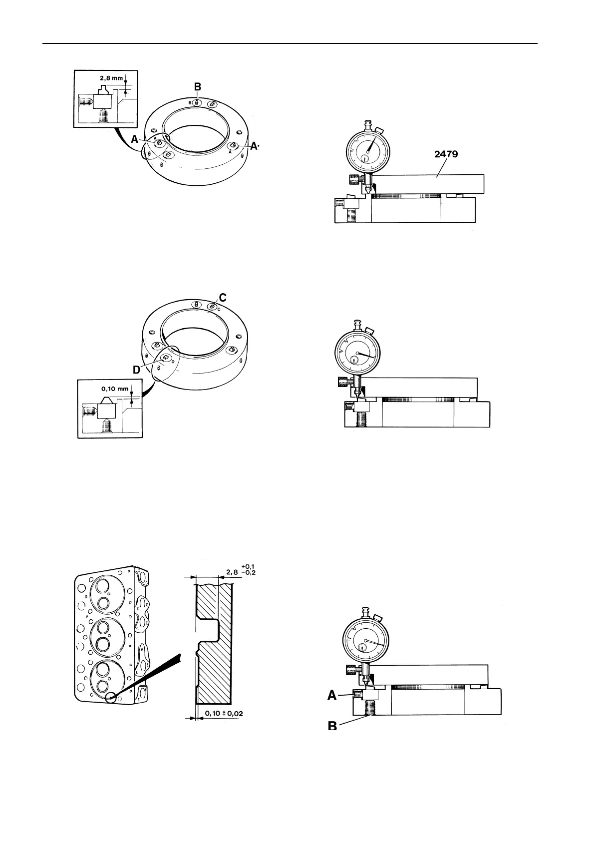
The remaining bits (marked C-D) are intended to work
the sealing plane, and should be adjusted to ±0.02
mm.
Sealing grooves in cylinder head.
3
The grooving tool has five bits. Three of them (Marked
A-A*-B) are intended to work the flame edge groove.
These should be adjusted to 2.8 mm +0.1, –0.2 mm.
Setting the cutters
Set up the cutter head in a vice, with the bits facing
upwards.
4
5
Slide the holder and dial gauge sideways so that the
gauge tip rests on the highest point of one of the cut-
ters, and read off the dial gauge.
Adjusting the bit
6
Undo lock screw “A” with a 4 mm Allen key, and turn
adjustment screw “B” a few turns with a 5 mm Allen
key.
Attach the dial gauge (998976) in holder 9992479 and
put this on the ring-shaped land on the cutting tool.
Zero the dial gauge against the land.