73
Wiring Diagrams
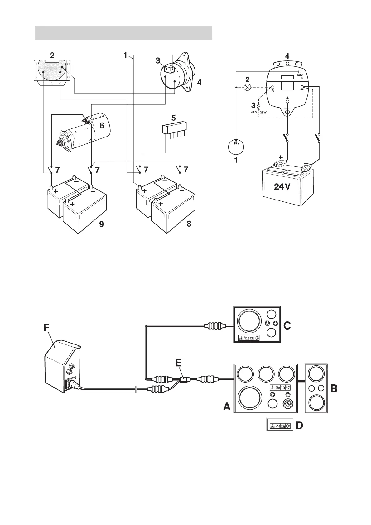
Connection of sensor system to standard generator,
principle diagram
1. Sensor cable (yellow, 1.5 mm
2
) 6. Starter motor
2. Charge distributor (accessory) 7. Main ON/OFF power switch
3. Voltage regulator 8. Accessory batteries (for
4. Generator accessories)
5. Fuse panel (accessory) 9. Start batteries (engine)
Block diagram
A. Main panel D. Alarm panel. (Used only when there is no main
B. Auxiliary panel panel A)
C. Flying Bridge panel* E. Y connection
F. Junction box** with fuses
* Main panel (A) may also be installed on the ** Note. The picture shows the TAMD63, TAMD73
flying bridge control position. and TAMD74.
Connecting the charge indicator lamp
Extra generator 28V/100A
1. Key switch
2. Charge indicator light
3. Resistor (47Ω/25W),
P/N 863400-8
4. Generator 28V/100A
7740156 - Downloaded from www.volvopenta.com 22/07/2009 00:44:08