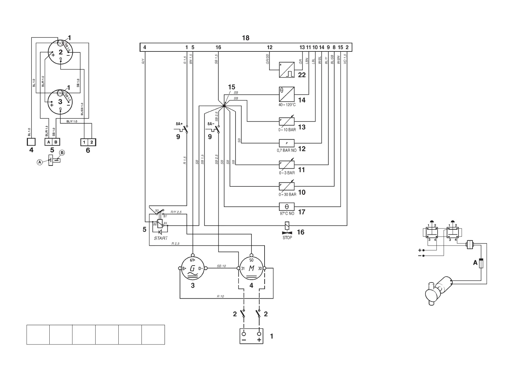
Auxiliary panel
1. Instrument lighting
2. Oil pressure gauge, reverse gear
3. Turbo charging pressure gauge
4. Connection to instr. light. on main
panel
5. Connection to printed circuit card
on main panel
6. Connection to connector (18) on
main panel
Conversions mm
2
/AWG*
*American Wiring Gauge
mm
2
1.0 1.5 2.5 10 16
AWG 16 (17) 15 (16) 13 7 5
Cable color
BL = Blue
LBL = Light-blue
BN = Brown
LBN = Light-brown
GN = Green
GR = Gray
OR = Orange
P = Pink
R = Red
SB = Black
VO = Violet
W = White
Y = Yellow
Engine
Note. The components in the wiring diagram
have the same numbers as shown in the
key diagrams on page 67.
1. Battery
2. Main ON/OFF power switch
3. Generator
4. Starter motor
5. Starter relay*
9. Semi-automatic fuses (8A) *
10. Oil pressure sender, reverse gear
11. Pressure sender, Turbo boost pressure
12. Oil pressure switch, engine
13. Oil pressure sender, engine
14. Engine coolant temperature sender
15. Ground terminal*
16. Fuel shut-off valve
17. Coolant temperature switch
18. 16-pin connector*
22. Engine speed (rpm) sender
*Located in the junction box
NO = Normally open during operation
A broken line indicates a non-Volvo
Penta cable.
Suggested connection of oil scaveng-
ing pump (pumping and filling)
Cable area 1.5 mm
2
.
A. Fuse (8A/24V, or 15A/12V)
7740156 - Downloaded from www.volvopenta.com 22/07/2009 00:44:08
 Loading...